In the realm of industrial automation and electrical engineering, proximity sensors are indispensable components for non-contact detection. Their representation in electrical schematics, through standardized symbols, is crucial for clear communication and accurate system design. These symbols convey not only the basic function but also the specific type and operational characteristics of the sensor, enabling engineers and technicians worldwide to interpret circuit diagrams uniformly.
The foundation for these graphical representations is established by international standards, primarily the IEC (International Electrotechnical Commission) 60617 series. This standardization ensures that a symbol used in a schematic in one country is understood identically in another. The basic symbol for a proximity sensor, regardless of its underlying technology, often resembles a diamond shape or a rectangle with a distinctive internal marker. This shape is typically embedded within the circle that denotes a general sensing device.
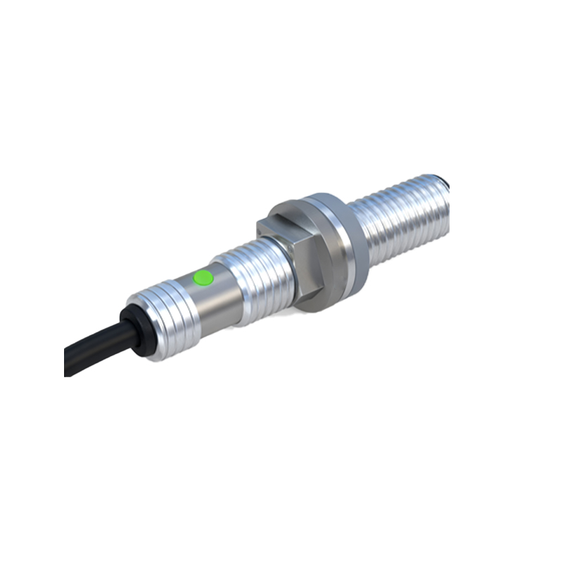
However, the critical detail lies within or adjacent to this basic shape. Different symbols distinguish between the primary sensing technologies. The most common types include:
Inductive Proximity Sensors: Represented by a coil symbol (a series of loops or a zigzag line) inside the sensor body. This directly indicates its principle of operation: generating an electromagnetic field to detect metallic objects. The symbol does not specify the metal type (ferrous or non-ferrous), which is a detail found in the accompanying datasheet.
Capacitive Proximity Sensors: Depicted with two parallel lines or plates inside the sensor symbol, representing the capacitive plates. This signifies its ability to detect both metallic and non-metallic materials (plastics, liquids, wood) by measuring changes in capacitance.
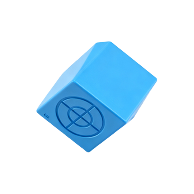
Ultrasonic Proximity Sensors: Often shown with a symbol resembling sound waves (concentric arcs) emanating from the device. This clearly denotes the use of ultrasonic sound waves for distance measurement and object detection.
Photoelectric Sensors: While sometimes categorized separately, their proximity versions use a symbol combining a light source (diode symbol) and a receiver. Variants (through-beam, retro-reflective, diffuse) may have slight symbolic modifications.
Beyond the sensing technology, the schematic symbol must also indicate the sensor's output type and switching function. This is typically denoted by the standard electrical switch symbols placed in line with the sensor's output terminals.
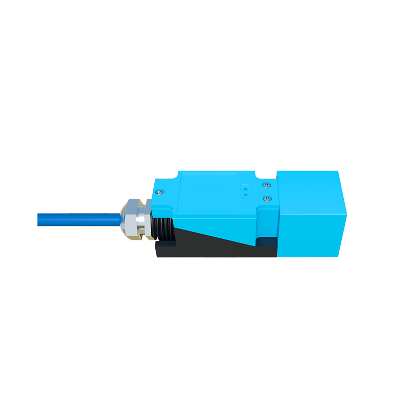
Normally Open (NO) Contact: Represented by a switch symbol that is open in its non-activated state. The switch closes when a target is detected.
Normally Closed (NC) Contact: Represented by a switch symbol that is closed in its non-activated state. The switch opens when a target is detected.
PNP vs. NPN Sourcing: For 3-wire DC sensors, the output transistor type (PNP or NNP) is not always explicitly shown in the basic symbol but is defined in the component legend or bill of materials. The wiring diagram adjacent to the schematic clarifies the sourcing (positive switch) or sinking (negative switch) configuration.
Furthermore, symbols may include additional graphical elements to specify form factors like cylindrical barrels or rectangular blocks, though the functional symbol remains the primary focus. Arrows might be used to indicate the sensing direction or field. It is also common to find alphanumeric designators next to the symbol, such as "B" for a sensor, followed by a number (e.g., B10, B11), as per IEC 81346-2 standards for component identification.
A precise understanding of these symbols is vital for several reasons. First, it allows for the correct integration of the sensor into the control logic. Misinterpreting an NC symbol as an NO, for instance, could lead to a dangerous failure in a safety interlock circuit. Second, it aids in troubleshooting. A technician analyzing a malfunctioning machine can trace the sensor's expected behavior directly from the schematic. Third, it facilitates efficient design and documentation, ensuring that procurement and installation teams source and mount the correct device.
In practice, engineers always cross-reference the schematic symbol with the manufacturer's datasheet. The symbol provides the functional and electrical interface, while the datasheet supplies the critical specifications: sensing range, supply voltage, output current, housing material, temperature rating, and connection details. Modern E-CAD software libraries contain extensive collections of these standardized symbols, but the onus remains on the designer to select the appropriate one that matches the chosen physical component.
In conclusion, proximity sensor symbols are far more than simple drawings; they are a concise, standardized language. They encapsulate complex technological functionality into a universally recognized visual code. Mastery of this symbolic language is a fundamental skill for any professional involved in designing, installing, or maintaining automated electrical systems, ensuring clarity, safety, and efficiency from the drawing board to the factory floor.