Inductive proximity sensors have become indispensable components in modern industrial automation, particularly for cylinder position detection in pneumatic and hydraulic systems. These non-contact sensing devices offer reliable, maintenance-free operation in harsh industrial environments where mechanical limit switches would fail prematurely. As an electrical engineer with decades of field experience, I've witnessed the evolution of these sensors from basic detection tools to sophisticated components integrated into Industry 4.0 systems.
The fundamental operating principle of inductive proximity sensors revolves around electromagnetic induction. When powered, the sensor generates an alternating electromagnetic field from its oscillator circuit. When a metallic target (typically the piston within a cylinder) enters this detection field, eddy currents are induced in the target material. These eddy currents draw energy from the oscillator, causing amplitude reduction that triggers the sensor's output circuit to change state. This entire process occurs without physical contact, eliminating mechanical wear and enabling millions of reliable switching cycles.
For cylinder applications, engineers typically select barrel-style inductive sensors that mount directly into cylinder mounting grooves or separate sensor brackets. The most common detection method involves sensing the piston itself or a metallic trigger (often called a "piston ring" or "sensor flag") attached to the piston rod. Modern cylinders frequently incorporate built-in sensor slots with standardized dimensions according to ISO 21287 or VDMA 24562 norms, ensuring compatibility with sensors from multiple manufacturers.
Key selection criteria for cylinder applications include sensing distance, switching frequency, housing material, and electrical characteristics. Sensing distance, typically ranging from 1mm to 15mm for cylinder applications, must be selected with consideration for installation tolerances and target material. Switching frequencies up to 5kHz allow detection in high-speed applications. Stainless steel or nickel-plated brass housings provide corrosion resistance in challenging environments. Electrical considerations encompass voltage ranges (commonly 10-30V DC or 20-250V AC), output types (PNP/NPN, NO/NC), and protection circuits against short-circuit, overload, and reverse polarity.
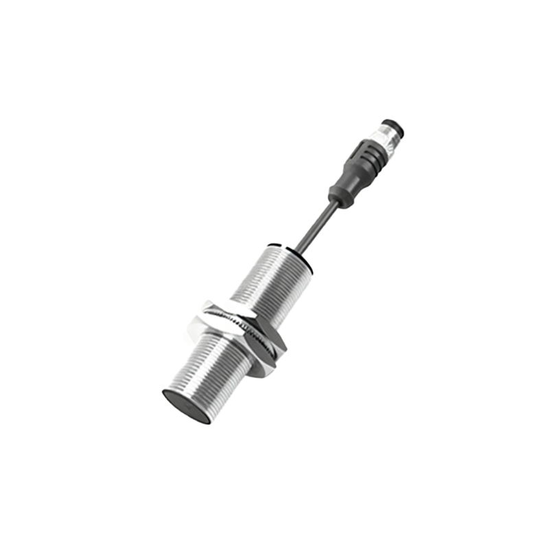
Installation practices significantly impact sensor performance and longevity. Proper alignment between sensor face and target is critical, as inductive sensors exhibit reduced effective sensing distance when targets approach from the side. Environmental factors including temperature extremes, cutting fluids, metal chips, and electromagnetic interference must be considered during sensor selection and installation. Shielded (flush-mountable) sensors offer protection against adjacent metallic surfaces but have shorter sensing ranges, while unshielded (non-flush) sensors provide longer ranges but require more installation clearance.
Advanced features in contemporary inductive sensors include IO-Link communication, diagnostic capabilities, and adjustable sensing parameters. IO-Link enabled sensors can transmit detailed operational data to control systems, facilitating predictive maintenance and process optimization. Some models incorporate temperature monitoring, switch point drift detection, and contamination warnings. For applications requiring precise position feedback, analog output sensors provide continuous distance measurement rather than simple on/off switching.
Troubleshooting common issues involves systematic approach. False triggering often results from improper grounding, electromagnetic interference, or metallic debris accumulation. Failure to detect typically indicates incorrect sensor-to-target distance, wrong target material, or damaged cabling. Regular maintenance should include visual inspection for physical damage, cleaning of sensing faces, and verification of electrical connections. Diagnostic tools ranging from simple LED indicators to sophisticated software interfaces help identify issues before they cause production downtime.
The integration of inductive sensors with programmable logic controllers (PLCs) has standardized through various connection methods. Two-wire sensors simplify installation but require careful consideration of leakage current. Three-wire and four-wire sensors provide separate power and signal lines, offering better performance in most applications. Quick-disconnect connectors versus fixed cable entries present another selection consideration based on maintenance requirements and environmental conditions.
Looking toward future developments, miniaturization continues to enable sensors for smaller cylinders while maintaining performance. Enhanced immunity to electromagnetic interference supports operation near variable frequency drives and welding equipment. Energy-efficient designs reduce overall system power consumption. Wireless configurations are emerging for difficult-to-wire applications, though power constraints currently limit their adoption in continuous operation scenarios.
In conclusion, proper selection, installation, and maintenance of inductive proximity sensors for cylinder applications require understanding both theoretical principles and practical constraints. These robust devices, when correctly applied, provide years of reliable service, contributing to increased machine uptime, improved safety, and enhanced process control in automated systems across manufacturing, packaging, automotive, and countless other industries.