In industrial automation and control systems, proximity switch sensors are indispensable components for detecting the presence or absence of objects without physical contact. Among various designs, sensors with copper shells are particularly valued for their excellent electromagnetic shielding, durability, and corrosion resistance. This article provides a comprehensive guide to the wiring diagram for proximity switch sensors with copper shells, covering key principles, standard configurations, and practical installation tips.
A typical proximity switch sensor with a copper shell consists of several core parts: the sensing face, oscillator circuit, trigger circuit, output switching element, and connection terminals enclosed in the copper housing. The copper shell not only protects internal electronics from environmental factors like moisture, dust, and chemical exposure but also minimizes electromagnetic interference (EMI), ensuring stable operation in electrically noisy environments such as factories or machinery setups.
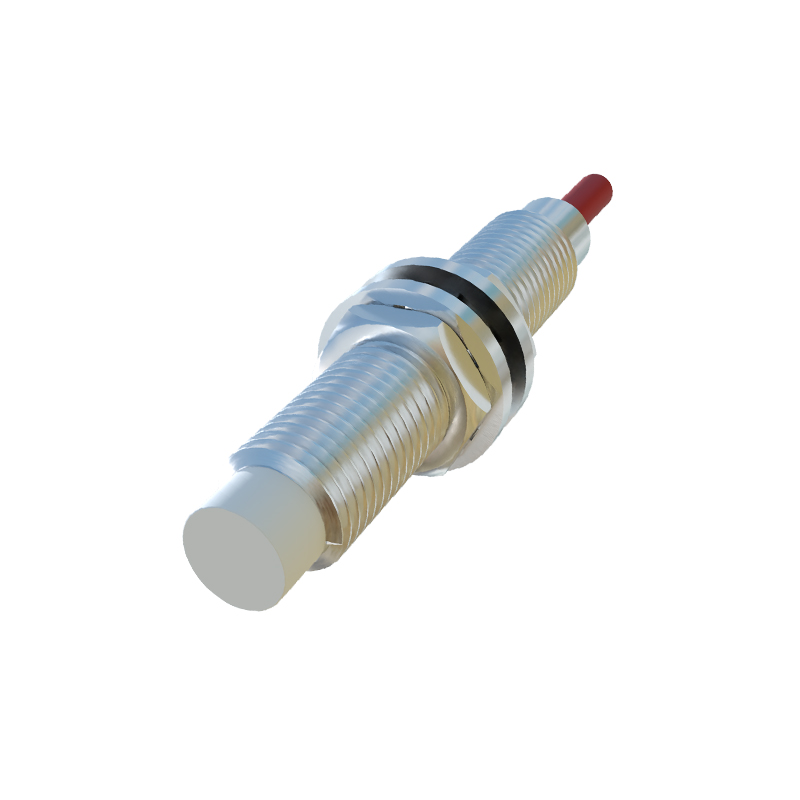
The wiring diagram generally includes three or four wires, depending on whether the sensor is AC or DC powered and its output type (e.g., NPN or PNP). For a standard 3-wire DC sensor with a copper shell, the wires are color-coded: brown for positive supply voltage (V+), blue for negative or ground (0V), and black for the output signal. In a 4-wire configuration, an additional white wire may be used for a second output or function, such as a normally closed (NC) contact. The copper shell itself is often connected to ground via a separate terminal or integrated into the mounting bracket to enhance shielding.
When interpreting the wiring diagram, start by identifying the power supply requirements. Most copper-shell sensors operate on DC voltages ranging from 10-30V DC or AC voltages like 90-250V AC. Ensure the power source matches the sensor's specifications to prevent damage. Next, connect the supply wires: attach the brown wire to the positive terminal and the blue wire to the negative terminal of the power supply. The output wire (black) should be linked to the load, such as a PLC input, relay coil, or indicator light. If the sensor includes a ground connection for the copper shell, secure it to a common ground point to optimize EMI protection.
For NPN-type sensors, the output switches the negative side of the load, meaning the load is connected between the positive supply and the sensor's output. Conversely, PNP-type sensors switch the positive side, with the load placed between the output and ground. Always verify the sensor's output type from its datasheet before wiring to avoid circuit malfunctions. Additionally, consider incorporating protective devices like fuses or surge suppressors in the wiring to safeguard against overcurrent or voltage spikes, especially in harsh industrial settings.
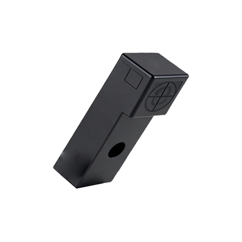
Installation practices are crucial for reliable performance. Mount the copper-shell sensor securely using appropriate brackets, ensuring the sensing face is unobstructed and aligned correctly with the target object. Maintain the recommended sensing distance—usually specified as the nominal range—to avoid false triggers. Since copper is conductive, avoid short circuits by insulating the shell from other metal parts unless grounding is intended. After wiring, test the sensor by bringing a target object within its detection range and checking the output signal with a multimeter or PLC monitor.
Common issues in wiring include reversed polarity, loose connections, or interference from adjacent machinery. Double-check all connections against the diagram, and use shielded cables if the sensor is installed near high-frequency devices. Regular maintenance, such as cleaning the copper shell to prevent oxidation and inspecting wires for wear, can extend the sensor's lifespan.
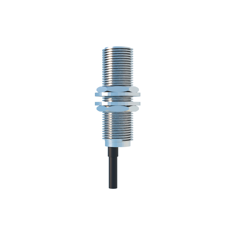
In summary, understanding the wiring diagram for proximity switch sensors with copper shells is essential for effective integration into control systems. By following standard color codes, adhering to power and output specifications, and implementing proper grounding and shielding, engineers can ensure accurate detection and long-term reliability. These sensors, with their robust copper housing, are ideal for demanding applications where precision and resilience are paramount.