In industrial automation and control systems, proximity sensors are indispensable components for non-contact detection of metallic objects. Among the various types available, 3-wire DC sensors are widely favored for their reliability, fast response, and precise switching characteristics. However, specific application scenarios or legacy control panel designs may necessitate the use of a 2-wire sensor configuration. This article provides a comprehensive technical guide for engineers on the principles, methodologies, and critical considerations for effectively converting or interfacing a 3-wire proximity sensor into a 2-wire system.
The fundamental distinction lies in the internal circuitry and wiring. A standard 3-wire DC proximity sensor typically comprises three leads: a brown wire for DC positive supply (V+), a blue wire for DC common or negative (V- or 0V), and a black wire as the switched output. This design uses a transistor (often an NPN or PNP type) as the solid-state switching element. The output transistor is separate from the power supply lines, allowing for low leakage current (often called residual current) and enabling direct interfacing with programmable logic controller (PLC) inputs or other sensitive electronic controls. The sensor's internal oscillator and detection circuit are powered directly between the brown and blue wires.
Conversely, a true 2-wire sensor has only two connection points. It is wired in series with the load (e.g., a relay coil or PLC digital input) and the power supply. Its internal electronics are designed to operate with the small quiescent current that flows through the load even in the "off" state. The switching is often accomplished using a solid-state device like a thyristor or a specially configured transistor that can handle the main load current. The key challenge when trying to use a 3-wire sensor in a 2-wire context is that its internal circuit is not designed to be powered through the load; it expects a dedicated power connection.
Therefore, a direct physical conversion of the sensor itself is not feasible or recommended, as it would require significant internal circuit redesign. The practical engineering solution involves using an external interface or adaptation method. The most common and reliable approach is to employ a dedicated interface relay. Here’s the standard procedure: The 3-wire sensor is powered normally (brown to V+, blue to V-). Its output wire (black) is then used to control the coil of a small, high-sensitivity relay. The relay coil is connected between the black wire and V- (for an NPN sinking output) or V+ (for a PNP sourcing output), with due consideration for flyback diode protection. The contacts of this relay (normally open or normally closed as required) are then used in the 2-wire loop. This method effectively isolates the sensor's electronics from the load circuit and is highly robust.
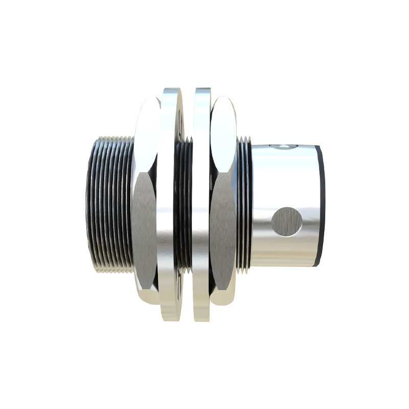
For a more integrated solution, one can use a solid-state interface module designed for this purpose. These compact modules accept the output from a 3-wire sensor and provide a 2-wire compatible output. They internally manage the power separation and often include features like overload protection and status indicators. This option is space-efficient and eliminates the mechanical wear associated with relay contacts.
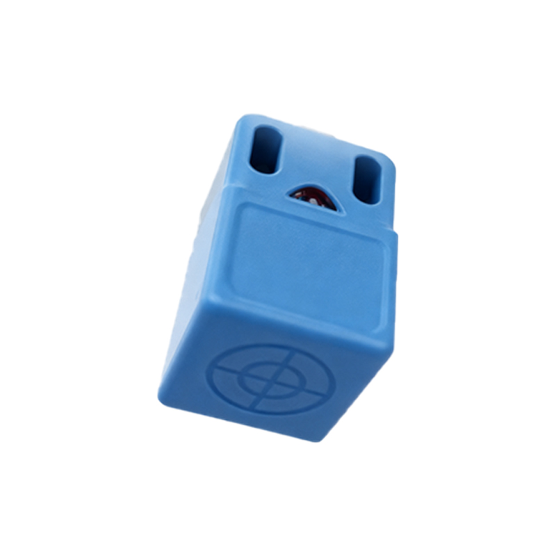
Several critical factors must be meticulously evaluated during implementation. First is the Voltage Drop and Minimum Operating Current. When a device is placed in series in a 2-wire circuit, it exhibits a voltage drop when "on" and allows a small leakage current when "off." The external relay or interface module must be chosen so that its "on" voltage drop does not deprive the load of sufficient voltage to operate. Simultaneously, its "off" leakage current must be below the threshold that would inadvertently activate the load (a crucial consideration for PLC inputs). Second, Load Compatibility is paramount. The adapted system must be compatible with the electrical characteristics of the load—whether it's an AC or DC coil of a contactor, a PLC digital input module (typically requiring a specific minimum "on" current), or a lamp. Third, Sensor Type (NPN vs. PNP) dictates the wiring of the interface device. An NPN sensor switches the negative side, while a PNP switches the positive side; the interface circuit must be configured accordingly to ensure correct operation. Finally, Environmental and Safety Considerations such as electrical noise, short-circuit protection, and compliance with safety standards (e.g., IEC 60947-5-2) must not be overlooked.
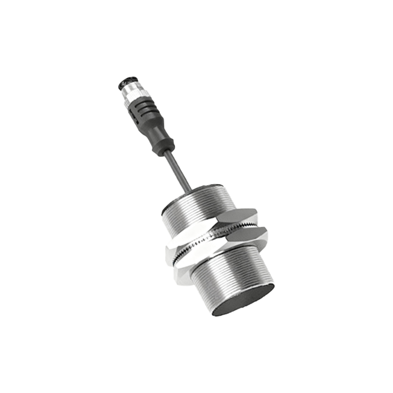
In summary, while a 3-wire proximity sensor cannot be internally modified into a 2-wire device, it can be successfully integrated into a 2-wire control loop using an external interfacing component like a relay or a specialty module. This approach leverages the performance benefits of 3-wire sensors while meeting the constraints