In the world of industrial automation, proximity sensors are indispensable components for non-contact detection of metallic and, in some cases, non-metallic objects. Among the various types, the 2-wire DC proximity sensor stands out for its simplicity and cost-effectiveness. However, its seemingly straightforward wiring can be a source of confusion and operational issues if not understood correctly. This guide provides a clear, practical walkthrough for engineers and technicians on properly wiring and integrating these ubiquitous sensors into a control system.
Unlike their 3-wire counterparts, which have separate wires for power, ground, and signal, a 2-wire sensor integrates its switching element directly into the power line. It functions essentially as a variable resistor or a switch that modulates the current flow in the same two wires used to power it. This design reduces wiring complexity and cost but introduces specific considerations for proper operation.
The fundamental principle is simple: the two wires are connected in series with the load (e.g., a PLC input module, a relay coil). One wire connects to the positive DC supply voltage (typically 10-30V DC), and the other wire connects to the load, which is then connected to the DC common (0V). When a target enters the sensor's sensing range, the internal electronic switch closes (for a normally open, NO, sensor), allowing current to flow through the sensor, through the load, and back to the power supply, thus activating the load. The sensor itself requires a small "quiescent" or "leakage" current (usually under 2 mA) to remain operational even when in the "off" state.
This leakage current is the most critical aspect of 2-wire sensor wiring. If the load's impedance is too high, this small leakage current may not be enough to create a voltage drop significant enough to be reliably detected as an "OFF" state by the PLC input. Conversely, when the sensor is active ("ON"), it has a voltage drop across its terminals (the "residual voltage" or "voltage drop," typically 1.5-3V). This voltage is lost and not available to the load. Both factors must be carefully checked against the specifications of the programmable logic controller (PLC) input module or the relay being used.
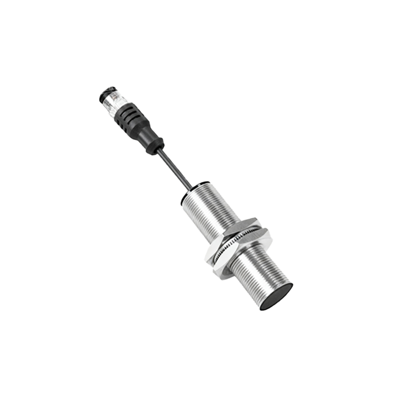
Here is a step-by-step wiring procedure:
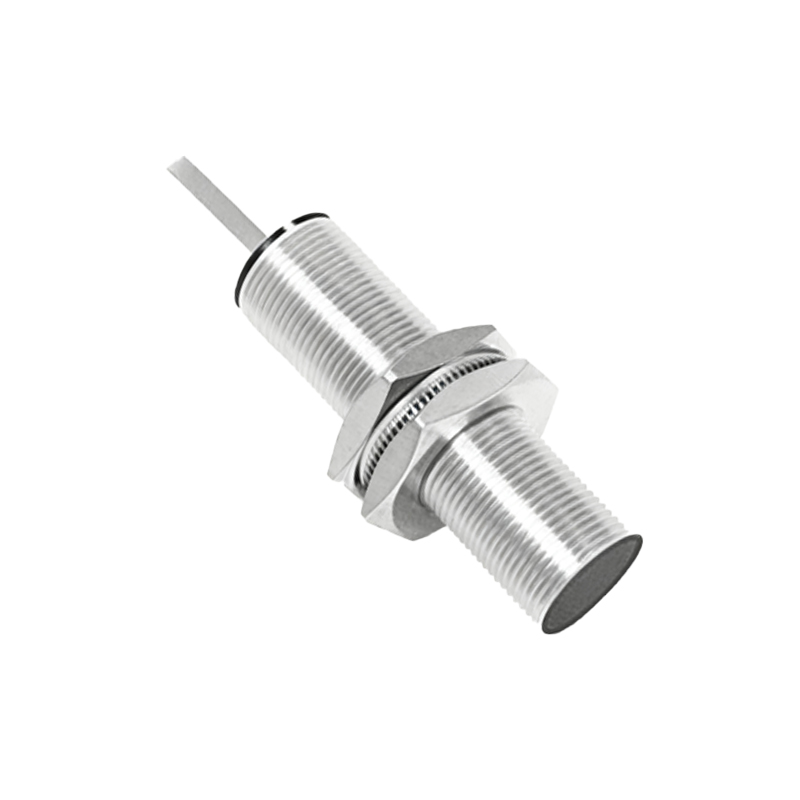
1. Verify Specifications: Before any connection, confirm the sensor's operating voltage (e.g., 10-30V DC), its output type (Normally Open/NO is most common), its leakage current, and its voltage drop. Simultaneously, check the PLC input module's specifications, particularly its "ON" voltage threshold (minimum voltage to register a logic 1) and its "OFF" voltage threshold (maximum voltage to register a logic 0), as well as its input impedance.
2. Power Off: Always disconnect power to the circuit before making connections.
3. Connect in Series: Connect one sensor wire (usually brown or red) to the positive DC supply terminal (e.g., +24V). Connect the other sensor wire (usually blue or black) directly to one terminal of your load (the PLC input point). Finally, connect the other terminal of the PLC input to the DC common or 0V terminal.
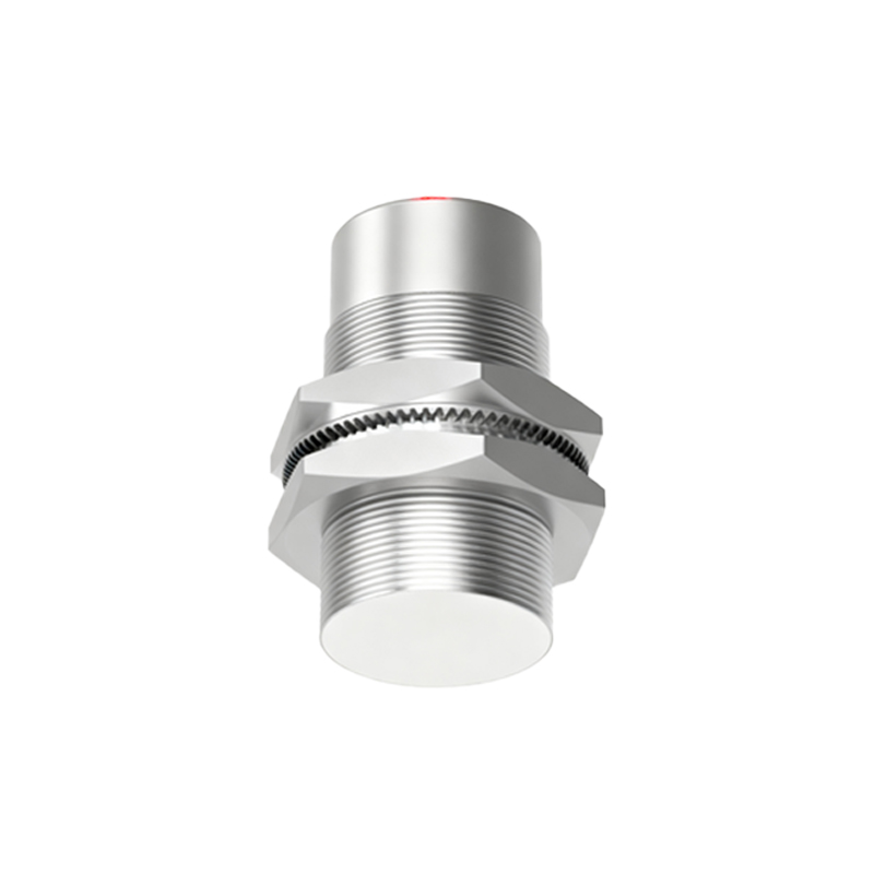
4. Consider Polarity: Most modern 2-wire DC sensors are protected against reverse polarity, but it is a best practice to connect brown/red to positive and blue/black to the load as per IEC standards.
5. Add a Bypass/Shunt Resistor (If Required): If the PLC input module has a very high impedance, the sensor's leakage current might not pull the input voltage low enough to be seen as "OFF." This can cause the input to remain in an indeterminate or falsely "ON" state. To solve this, a bypass (or shunt) resistor is installed in parallel with the PLC input. A common value is 10kΩ to 47kΩ, 1W. This resistor provides a path for the leakage current, creating a definitive voltage drop below the PLC's OFF threshold. Calculate the resistor value based on the leakage current and the PLC's OFF voltage limit.
6. Account for Voltage Drop: Ensure that the voltage at the PLC input, when the sensor is active, is still above the module's guaranteed "ON" level. For example, with a 24V supply and a sensor drop of 3V, the PLC input sees ~21V, which is usually sufficient.
7. Test the Circuit: Apply power. Use a multimeter to measure the voltage at the PLC input terminals. With no target present, it should read a very low voltage (ideally under 3V, depending on the shunt resistor).