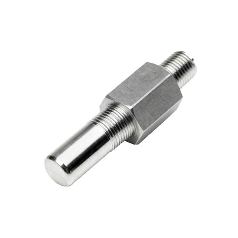
Voltage measurement is a fundamental diagnostic step when working with proximity switch sensors in industrial automation and electrical systems. As an experienced electrical engineer, I often encounter situations where a sensor's performance is questioned, and the first step is always to verify its power supply and output signal integrity by checking the voltage. This guide provides a systematic, industry-standard approach to this critical task.
First and foremost, safety is paramount. Before any measurement, ensure the control circuit is properly locked out and tagged out (LOTO) according to your facility's safety procedures. Verify the sensor's specifications from its datasheet or nameplate. Key parameters include the operating voltage range (commonly 10-30V DC for DC sensors, or 20-250V AC for AC types), output type (PNP/NPN sourcing/sinking for DC, or relay/SSR for AC), and whether it is a 2-wire, 3-wire, or 4-wire device. This information dictates your measurement strategy.
For a standard 3-wire DC proximity sensor (the most common type), you will typically have a brown wire (+V), a blue wire (0V/Common), and a black wire (signal output). To check the supply voltage, set your digital multimeter (DMM) to the appropriate DC voltage range, likely the 20V or 200V DC scale. Place the black probe on the blue wire (or a verified system common/ground point) and the red probe on the brown wire. The reading should be within the sensor's specified range, typically 24V DC ±10%. A reading of zero indicates a blown fuse, tripped circuit breaker, or wiring fault upstream. A reading significantly low suggests a possible short circuit or overloaded power supply.
The next critical measurement is the output voltage. The procedure differs for PNP (sourcing) and NPN (sinking) sensors. For a PNP sensor, with the sensor powered, place your DMM's black probe on the blue wire (0V). Place the red probe on the black output wire. When the sensor is in its normal state (not detecting a target), the output should be near 0V (OFF state). Actuate the sensor by bringing the specified target material within its sensing range. The voltage on the black wire should now read close to your supply voltage (e.g., ~24V), indicating the output is switched ON. For an NPN sensor, the logic is inverted. The black output wire will switch to near 0V (sink current) when the target is detected. It is crucial to have a load (like a PLC input or a test resistor) connected during this test, as some solid-state outputs require a load to function correctly and provide a measurable voltage.
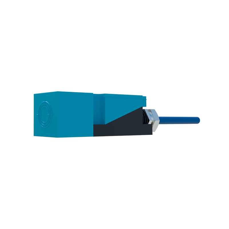
For 2-wire AC or DC sensors, the sensor is in series with the load. To check voltage, measure across the load (e.g., a PLC input module or a relay coil) with the DMM set to the correct AC or DC range. With no target present, you should measure near full supply voltage because the sensor's internal impedance is high (OFF state). When a target actuates the sensor, it switches to a low-impedance state, and the voltage across the load should drop significantly, allowing current to flow and energize it. A residual high voltage (e.g., >15V AC on a 120V AC circuit) when the sensor is ON indicates a failing sensor that cannot pass sufficient current.
Common pitfalls include measuring without a proper load, leading to misleading "ghost" voltages on high-impedance digital meters. Using a solenoid voltage tester or connecting a small pilot light (e.g., 24V LED) in parallel with your probes can confirm the output's current-sourcing capability. Also, remember that analog or IO-Link sensors provide a variable voltage or digital signal, requiring reference to their specific scaling documentation. Always check for voltage drops along long cable runs, especially when sensors are at the far end of a machine. A measurement at the power supply terminal and again at the sensor's terminals can reveal significant wiring losses.
In conclusion, methodically checking voltage at the supply points and the output terminal under both actuated and non-actuated conditions provides definitive evidence of a proximity sensor's electrical health. This data, combined with a visual inspection for damage and a check of the sensing distance, forms the core of effective sensor troubleshooting. Mastering this skill ensures minimal downtime and reliable operation of your automated systems.