In the realm of industrial automation and machinery condition monitoring, the selection of sensing technology is a critical decision that impacts efficiency, safety, and maintenance costs. Among the diverse array of sensors available, turbine proximity sensors hold a distinct position, particularly in rotational speed and position detection applications. This analysis delves into the operational principles, advantages, limitations, and ideal use cases of turbine proximity sensors to answer the fundamental question: are they a good choice?
At their core, turbine proximity sensors are non-contact devices designed to detect the presence, speed, and sometimes the direction of a rotating turbine blade or gear tooth. They typically operate on the principle of electromagnetic induction (eddy current) or, more commonly in modern variants, the Hall effect. As a ferromagnetic target—like a blade on a turbine rotor—passes through the sensor's magnetic field, it causes a measurable change. In a Hall-effect sensor, this change modulates the output voltage, generating a digital pulse for each passing blade. This pulse train is then processed by a controller or monitoring system to calculate rotational speed (RPM) or determine angular position with high precision.
The primary advantages of turbine proximity sensors are substantial and explain their enduring presence in demanding sectors like power generation (gas/steam turbines), aerospace (engine monitoring), and heavy industrial machinery.
First and foremost is their robustness and durability. Designed for harsh environments, high-quality turbine sensors are housed in stainless steel or similarly rugged casings, offering excellent resistance to vibration, mechanical shock, and extreme temperatures. They are inherently sealed against contaminants like oil, grease, and dust, often meeting IP67 or higher ingress protection ratings. This makes them suitable for installation directly on or near machinery without the need for complex protective enclosures.
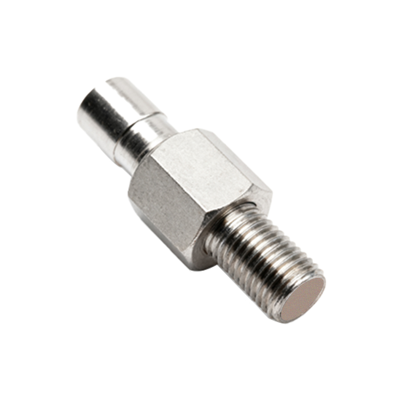
Secondly, they offer non-contact, wear-free operation. Unlike mechanical tachometers or switches that require physical contact, proximity sensors eliminate a source of friction and mechanical failure. There is no physical linkage to wear out, leading to significantly longer service life and reduced maintenance intervals. This non-contact nature also allows for measurement without applying any load to the rotating shaft, ensuring accuracy is not compromised by the measurement process itself.
High accuracy and fast response are other key benefits. These sensors can detect very high rotational speeds, often into the hundreds of thousands of RPM, with exceptional resolution. The digital pulse output provides a clean signal for precise speed calculation and is highly immune to electrical noise when properly installed and shielded. Their fast response time is crucial for critical applications like overspeed protection in turbines, where a millisecond delay can be catastrophic.
Furthermore, their relative simplicity and reliability are major assets. With no moving parts in the sensing element, the potential failure modes are minimized. The output is typically a straightforward two-wire or three-wire DC signal, simplifying integration into PLCs (Programmable Logic Controllers), SCADA systems, or dedicated protection relays.
However, to provide a balanced perspective, it is essential to consider their limitations. The performance of a turbine proximity sensor is highly dependent on proper installation and alignment. The gap (air gap) between the sensor tip and the target blade must be set precisely according to manufacturer specifications. An incorrect gap can lead to signal loss, reduced amplitude, or false triggering. The target geometry—the size, shape, and material of the blades or teeth—must also be compatible. They are generally designed to detect ferrous metals; detecting non-ferrous materials requires specialized sensor types.
Another consideration is their inherent "zero-speed" capability. While excellent for measuring rotational speed, a standard Hall-effect or eddy-current proximity sensor requires the target to be moving to generate a signal. It cannot typically provide a static position output when the turbine is stopped without additional indexing or reference markers. For absolute position detection at standstill, a resolver or encoder might be a necessary complement.
Environmental factors, while generally well-tolerated, can pose challenges. Extreme temperatures can affect the sensor's electronics, and very strong external magnetic fields could potentially interfere with operation, though shielding mitigates this.
So, are turbine proximity sensors good? The answer is a resounding yes, for their intended applications. They are an excellent, often optimal, choice for:
Speed Monitoring and Overspeed Protection: In turbines, compressors, engines, and large motors.
Condition Monitoring: Detecting changes in vibration signatures or rotational uniformity that indicate imbalance or blade damage.
Synchronization: Controlling the timing between multiple rotating elements.
Simple Position Sensing: In applications like camshaft or crankshaft timing where a repetitive pulse per revolution is sufficient.
In conclusion, turbine proximity sensors represent a mature, highly reliable, and performant technology for critical rotational measurement tasks. Their goodness is not universal but is exceptionally high within their design domain. When the