In the realm of industrial automation, precision is paramount. ELCO laser sensors, renowned for their high accuracy, reliability, and versatility, are critical components in applications ranging from object detection and positioning to thickness measurement and edge guiding. However, their superior performance is contingent upon proper installation, calibration, and ongoing maintenance. This guide provides a detailed, step-by-step approach to debugging and optimizing ELCO laser sensors, ensuring they operate at peak efficiency within your control systems.
The initial phase, often where issues originate, is installation and wiring. Before powering the sensor, meticulously verify the electrical connections against the datasheet. ELCO sensors typically offer multiple output types (e.g., NPN, PNP, analog, IO-Link) and supply voltage ranges (commonly 10-30V DC). Incorrect wiring can lead to immediate failure or erratic behavior. Ensure the power supply is stable and within specification, as voltage spikes or noise can interfere with the sensitive laser measurement circuitry. Proper grounding is non-negotiable; use shielded cables and connect the shield to a solid earth ground at the controller end to minimize electromagnetic interference (EMI). The physical mounting must be rigid and vibration-free. Even minor shifts can cause significant measurement drift. Align the sensor perpendicular to the target surface for distance measurement applications, and ensure the target is within the specified sensing range and field of view.
Once installed, proceed to parameter configuration, which is most efficiently done via the sensor's teach-in functions or dedicated software tools like ELCO's proprietary configuration suite. Begin by setting the basic operational mode: background suppression, retro-reflective, or through-beam, depending on your application. For analog sensors, calibrate the output scaling. Use the teach function to set the "near" and "far" points corresponding to the desired 4mA and 20mA (or 0V and 10V) outputs. For digital sensors with switching outputs, carefully adjust the trigger threshold. A common debugging mistake is setting the threshold too close to the normal signal variation, causing "chatter" or intermittent switching. Utilize the sensor's built-in LED indicators or monitor the analog signal on a PLC or oscilloscope to observe the stability of the received signal relative to your setpoint.
Environmental factors are a frequent source of problems. Laser sensors can be affected by ambient light, dust, steam, and temperature fluctuations. For high-ambient-light conditions, select models with modulated laser light or adjust the receiver's sensitivity. In dirty environments, regular lens cleaning is essential, as particulate buildup attenuates the laser beam. Use only approved, lint-free cloths and appropriate cleaners. Temperature changes can affect both the sensor's electronics and the target material's properties. If measurement drift correlates with shop floor temperature cycles, consider sensors with temperature compensation or implement software compensation in the PLC logic.
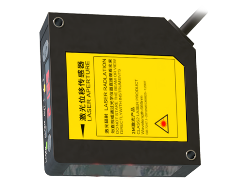
Systematic troubleshooting is key when a sensor malfunctions. Follow this logical flow:
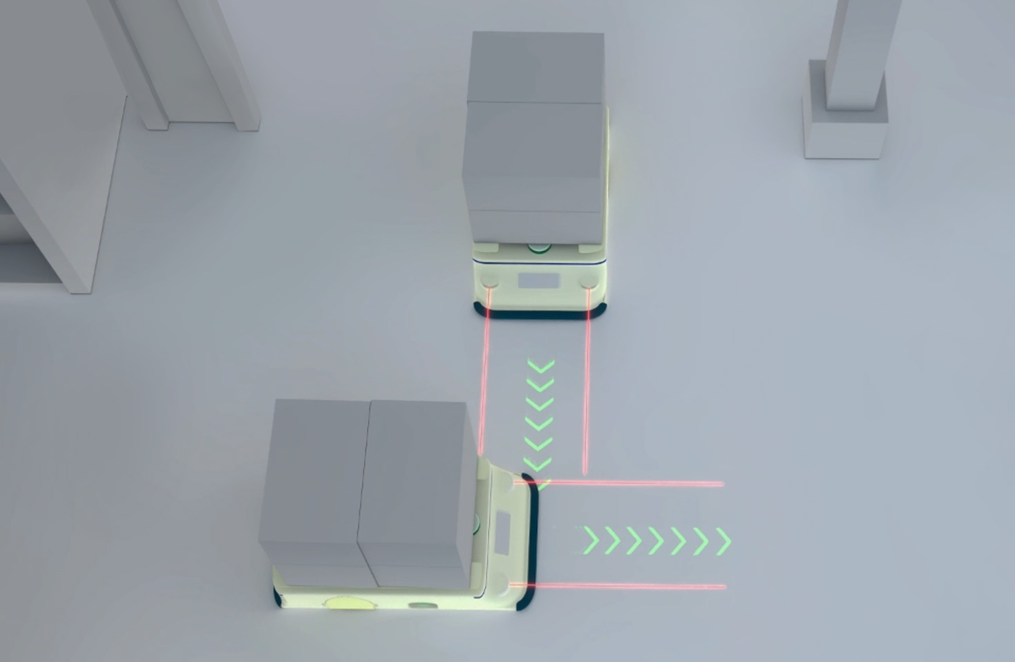
1. Power & Indicators: Is the power LED on? If not, check fuse, wiring, and supply voltage.
2. Output State: Is the output LED active or stuck? Monitor the actual output signal at the PLC input card or with a multimeter to distinguish between a sensor fault and a wiring/PLC input fault.
3. Signal Strength: Most ELCO sensors provide a way to monitor the received signal strength, often as a secondary analog value or via software. A weak or unstable signal indicates misalignment, dirty optics, an unsuitable target surface (e.g., transparent, shiny, or absorbent), or the target being outside the operational range.
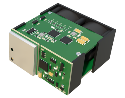
4. Interference: Temporarily isolate the sensor. Does the problem persist? Check for other lasers, high-frequency drives, or welding equipment causing interference.
5. Parameter Integrity: Power cycle the sensor. Sometimes, memory corruption can occur. Reload a known-good parameter set.
For advanced diagnostics, leverage communication protocols like IO-Link. IO-Link provides a wealth of real-time data: internal temperature, operating hours, signal quality, and detailed diagnostic messages. This enables predictive maintenance, allowing you to schedule cleaning or replacement before a failure causes downtime.
Finally, document all parameters, calibration points, and environmental conditions. This log is invaluable for replicating setups, training personnel, and accelerating future debugging sessions. Regular preventive maintenance—scheduled cleaning, connector inspection, and verification checks—will maximize the sensor's service life and measurement consistency. By adhering to these rigorous installation, calibration, and troubleshooting practices, engineers can fully harness the precision of ELCO laser sensors, ensuring robust and reliable performance in the most demanding industrial automation environments.