In industrial automation and precision control systems, the V20 proximity light sensor has become a cornerstone component due to its high sensitivity, robust construction, and reliable performance in diverse environmental conditions. Proper calibration of this sensor is not merely a recommended procedure—it is a critical step that directly impacts system accuracy, operational safety, and long-term stability. This guide provides a comprehensive, step-by-step approach to calibrating the V20 sensor, adhering to industry best practices and engineering principles.
Before initiating calibration, ensure the sensor is correctly installed in its intended operational environment. Verify that the mounting position aligns with the manufacturer's specifications, free from obstructions, vibrations, or external light interference that could skew readings. Power the sensor using a stable, regulated DC supply within its rated voltage range, typically 10-30 VDC, to prevent electrical noise or fluctuations from affecting calibration accuracy. Allow the sensor to warm up for approximately 15-20 minutes to reach thermal equilibrium, as temperature variations can influence optical components and electronic circuits.
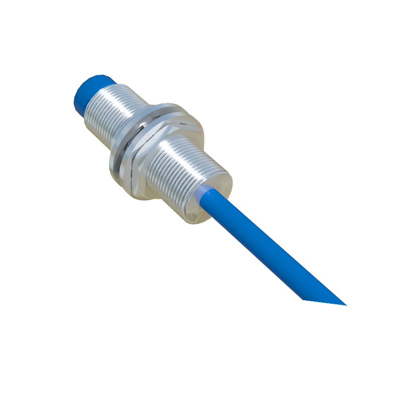
The calibration process begins with accessing the sensor's configuration mode, usually via a teach button or digital interface such as IO-Link, depending on the model variant. Connect a calibrated reference target—a standardized object with known reflectivity properties—at the exact sensing distance specified in the datasheet. For the V20, this is often set at the nominal sensing range, e.g., 20 mm for diffuse reflective types. Activate the calibration command while ensuring ambient lighting conditions mimic actual operating scenarios. Avoid direct sunlight or intense artificial light sources, as these can cause oversaturation or false triggers.
Adjust the sensitivity threshold using the potentiometer or software parameters until the sensor's output consistently toggles when the target enters and exits the detection zone. It is advisable to perform multiple test cycles, moving the target in and out gradually, to verify repeatability. Record the threshold value for future reference or fault diagnostics. For sensors with background suppression functionality, additional steps may include setting the suppression distance to ignore objects beyond a defined range, enhancing selectivity in cluttered environments.
Post-calibration validation is essential. Test the sensor with various materials and surface colors it will encounter in real applications, as reflectivity differences can affect performance. Measure response times and switching hysteresis to ensure they meet process requirements. Document all calibration settings, environmental conditions, and test results in a maintenance log. Regular recalibration is recommended every 6-12 months or after any mechanical shock, temperature extremes, or lens contamination, as these factors can drift sensor alignment or degrade optical clarity.
Common pitfalls during calibration include ignoring electrical grounding, which leads to electromagnetic interference, or using non-standard targets that deviate from specified reflectivity. Always consult the V20 technical manual for model-specific nuances, such as analog output linearization or teach-in procedures for programmable variants. In summary, meticulous calibration transforms the V20 from a generic component into a tailored solution, optimizing detection reliability and extending service life in demanding industrial settings.