Proximity sensor alarms are a common yet critical issue in industrial automation and control systems. These alarms, often indicated by flashing lights, audible beeps, or HMI notifications, signal that a sensor is not functioning within its specified parameters. Ignoring them can lead to unplanned downtime, production errors, or even equipment damage. This guide provides a systematic, engineer-level approach to diagnosing and permanently eliminating these disruptive alarms.
The first and most crucial step is to understand the alarm's specific nature. Modern proximity sensors, whether inductive, capacitive, or photoelectric, often communicate via discrete signals or through industrial networks like IO-Link. Consult the sensor's datasheet and the system's alarm code list. An alarm might indicate "Short Circuit," "Open Circuit," "Supply Voltage Out of Range," "Excessive Temperature," or "Sensor Drift." Identifying the exact error code immediately narrows down the potential root causes from dozens to a manageable few.
Step 1: Immediate Safety and Visual Inspection
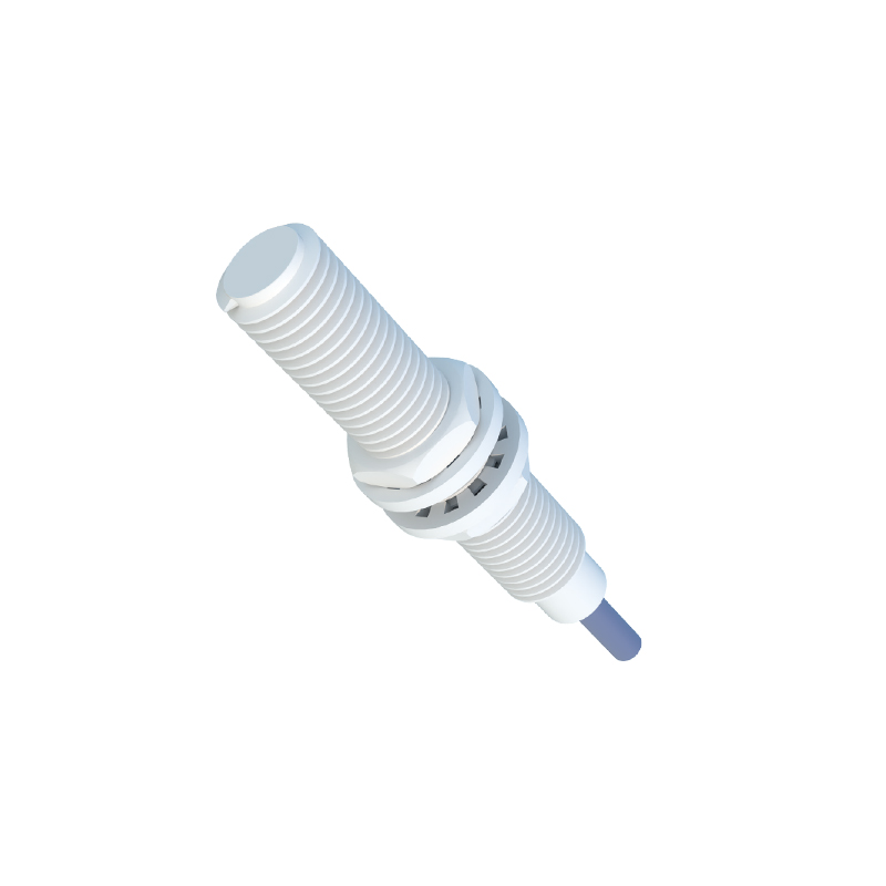
Before touching anything, follow lock-out/tag-out (LOTO) procedures to safely isolate the machine or circuit. Once safe, perform a thorough visual inspection.
Sensor Body: Check for physical damage, cracks, or signs of impact. Look for accumulated metal shavings (for inductive sensors), dust, oil, or coolant coating the sensing face. Even a thin layer can attenuate the signal.
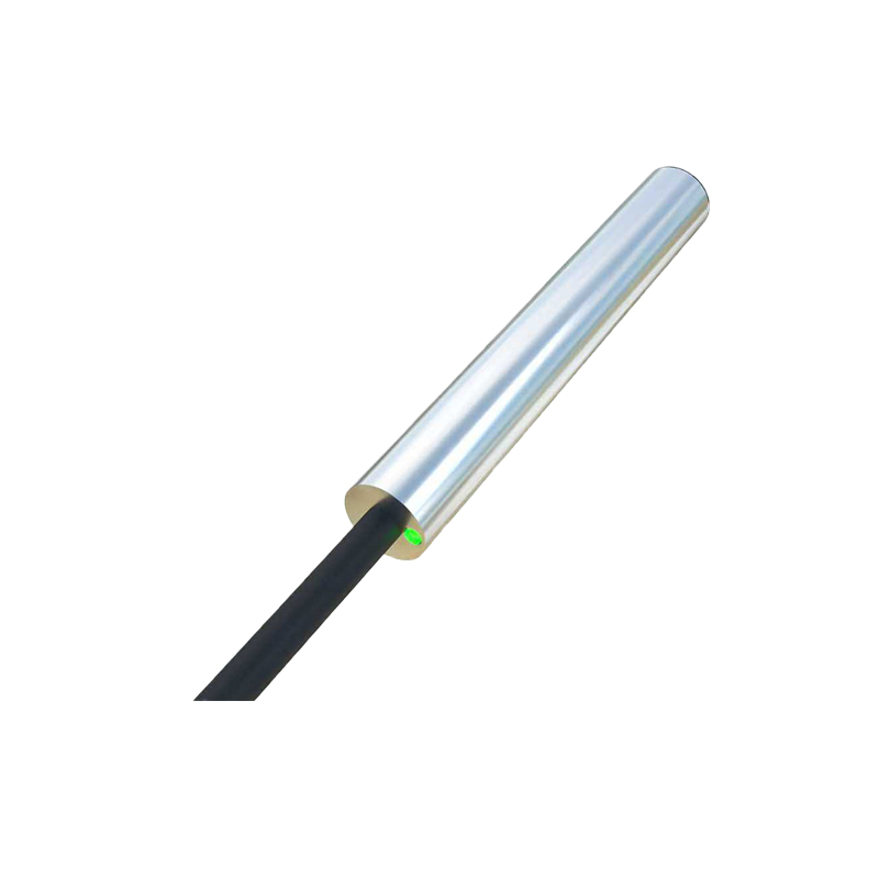
Wiring and Connections: Inspect the cable for cuts, pinch points, or abrasion. Examine the connector (e.g., M8, M12) for bent pins, corrosion, or moisture ingress. Ensure the cable gland is tight and properly sealed.
Mounting: Verify the sensor is securely mounted. Loose mounting can cause vibration-induced failures or change the critical sensing distance relative to the target.
Step 2: Electrical Diagnostics
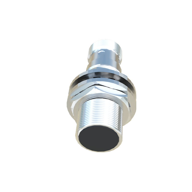
With a multimeter or process calibrator, verify the fundamental electrical conditions.
Supply Voltage (Vcc): Measure at the sensor's terminals. Compare it to the rated voltage (e.g., 10-30V DC). A voltage even 10% outside this range can trigger an alarm. Look for voltage drops caused by long cable runs or overloaded power supplies.
Output Load: Check the load (e.g., PLC input, relay coil) connected to the sensor's output. Ensure the current draw is within the sensor's switching capacity. An overloaded output can mimic a short-circuit fault.
Wiring Continuity and Insulation: Perform continuity tests on the signal and supply lines to check for breaks. Test for insulation resistance between wires and to ground to identify subtle shorts, especially in damp environments.
Step 3: Environmental and Application Factors
Often, the sensor is functional, but the application conditions have changed.
Target Characteristics: For inductive sensors, ensure the target is ferrous (for standard models) and of sufficient size. The effective sensing distance (Sn) can be reduced if the target is smaller than the sensor's face. For capacitive sensors, changes in material density or moisture content can cause false triggering.
Alignment and Distance: Re-measure the gap between the sensor and the target. Use a feeler gauge. The operating distance must be within 0-81% of the rated sensing distance to account for supply voltage and temperature tolerances. Misalignment can cause intermittent signals.
Interference: Electromagnetic interference (EMI) from nearby variable frequency drives (VFDs), motors, or welding equipment can induce noise in sensor cables. Ensure cables are shielded, and shield drains are properly grounded at one end only. Separate sensor cables from power lines.
Step 4: Sensor Configuration and Calibration
Many smart sensors have configurable parameters. Access these via push-buttons or software.
Teaching/Calibration: Some sensors allow "teaching" a new switch point. If the target material has changed, a re-teach procedure can resolve the alarm. For analog sensors, recalibrating the 4-20mA or 0-10V output range may be necessary.
Output Mode: Verify the output is set correctly (Normally Open/NO or Normally Closed/NC, NPN or PNP) to match the PLC's expected logic. A mismatch will cause the control system to interpret a correct signal as an alarm.
Hysteresis and Response Time: Incorrect hysteresis settings can cause "chatter" on the edge of the sensing field, perceived as an alarm. An overly fast response time might not be suitable for a vibrating target.
Step 5: Systematic Elimination and Permanent Fix
After identifying the probable cause, implement the fix.
Cleaning: Use a soft cloth and