In the realm of industrial automation and precision measurement, laser position sensors have established themselves as indispensable tools. Their ability to provide non-contact, high-accuracy measurements of distance, displacement, and position is fundamental to quality control, robotics, and assembly processes. However, a common operational scenario that presents unique challenges is when these sensors are mounted or required to operate at an angle relative to the target surface—a configuration we refer to as a tilted or oblique laser position sensor. This article delves into the principles, challenges, and practical considerations of using laser position sensors in such non-orthogonal setups.
At its core, a standard laser position sensor, often based on triangulation or time-of-flight principles, is calibrated for optimal performance when its laser beam is perpendicular to the target surface. In this ideal orthogonal alignment, the reflected light returns along a predictable path to the detector, allowing for straightforward calculation of position or distance. The introduction of a tilt angle disrupts this ideal geometry. When the sensor is tilted, the incident laser beam strikes the target at an oblique angle. This significantly alters the characteristics of the reflected light spot, including its shape, intensity distribution, and the angle of reflection. For triangulation sensors, this can cause the returning light spot to shift on the position-sensitive detector (PSD or CMOS/CCD) in a way not directly proportional to the pure distance change, leading to measurement errors, signal dropout, or reduced resolution.
The primary challenge stems from the cosine error. The measured displacement along the sensor's line-of-sight axis is related to the actual perpendicular displacement by the cosine of the tilt angle. For small angles, this error might be negligible, but as the angle increases, the discrepancy grows non-linearly. A 30-degree tilt, for instance, introduces a cosine error of approximately 13.4%. Without compensation, this renders measurements inaccurate. Furthermore, surface properties become critically more influential. A specular (mirror-like) surface can reflect the beam entirely away from the sensor's receiver at certain angles, causing a complete loss of signal. Even with diffuse surfaces, the effective intensity and spot shape change, potentially pushing the signal below the sensor's sensitivity threshold or causing erroneous centroid calculations.
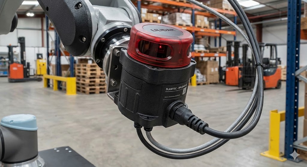
Despite these challenges, there are valid engineering reasons for employing a tilted sensor. Space constraints within machinery often preclude perpendicular mounting. Certain measurements, like step height or edge detection on a vertical surface, inherently require an angled approach. In some vibration analysis or alignment tasks, the tilt itself is the variable being measured. The key is to manage and mitigate the associated errors.
Successful implementation requires a multi-faceted approach. First, sensor selection is paramount. Some modern laser sensors are equipped with advanced optics and algorithms that offer a degree of tolerance to angled operation, often specified as a maximum allowable tilt angle in their datasheets. Second, meticulous calibration in the actual tilted configuration is non-negotiable. This involves creating a calibration curve specific to the exact tilt angle and target surface material, mapping the sensor's raw output to the true geometric values. Third, understanding the surface is crucial. For consistent results, the target surface should have a uniform, matte (Lambertian) finish to scatter light reliably back towards the sensor even at an angle. Application-specific fixtures or mounting brackets that ensure a precise and repeatable tilt angle are also essential for stability.
From an application perspective, tilted laser sensors find use in specialized scenarios. In automotive assembly, they might be angled to measure the flushness of door panels or the gap between body parts. In electronics manufacturing, an angled sensor can profile the sides of components on a board. In roll diameter measurement, sensors are often tilted to avoid physical obstruction and to measure the chord length, from which the diameter is calculated.

In conclusion, operating a laser position sensor at a tilt is a deviation from its ideal condition but a common and manageable one in practical engineering. It introduces geometric complexities and demands greater attention to calibration, surface interaction, and sensor specifications. By thoroughly analyzing the application geometry, selecting an appropriate sensor model, and performing rigorous in-situ calibration, engineers can effectively harness the power of laser position sensing even in oblique configurations, ensuring precision is maintained where straight-on measurement is not an option. The decision to tilt a sensor should always be a calculated one, weighing the spatial and functional benefits against the need for increased setup diligence and potential trade-offs in accuracy or signal strength.