In the realm of industrial automation and electrical control systems, proximity sensors are indispensable components for non-contact detection of objects. Their correct installation and wiring are paramount for ensuring system reliability, safety, and optimal performance. This article provides an in-depth look at proximity sensor wiring diagrams, emphasizing the importance of high-definition images for accurate interpretation and implementation. We will explore common wiring configurations, key symbols, and best practices for electrical engineers and technicians.
Understanding the wiring diagram is the first critical step. A high-definition (HD) wiring diagram image offers clarity, allowing you to discern fine details such as terminal numbers, wire color codes, and component symbols without ambiguity. Blurry or low-resolution images can lead to misinterpretation, potentially causing wiring errors, sensor damage, or machine malfunction. Always source diagrams from the sensor manufacturer's official documentation or reputable technical portals.
Proximity sensors primarily fall into two categories based on their output type: 2-wire, 3-wire, and sometimes 4-wire models. The wiring differs significantly.
1. 3-Wire DC Proximity Sensors: This is the most common type. An HD diagram will clearly show three distinct wires:
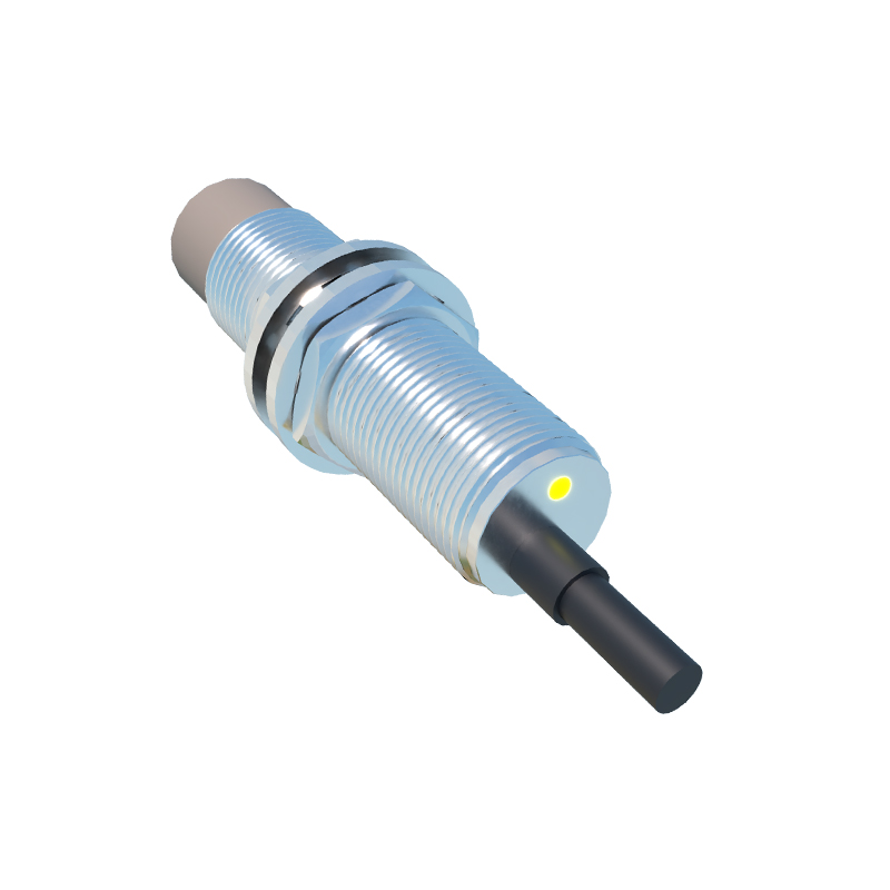
Brown Wire: Typically connected to the positive DC supply voltage (e.g., +24VDC).
Blue Wire: Typically connected to the negative DC supply voltage or 0V (Common).
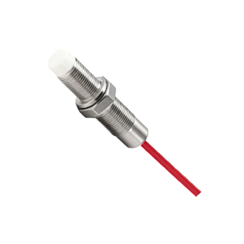
Black Wire: The output signal wire. The diagram must specify if the sensor is NPN (sinking) or PNP (sourcing). For an NPN sensor, the black wire switches the load to ground (0V). For a PNP sensor, it switches the load to the positive supply.
A high-quality diagram will include symbols for the power supply, the sensor, and the load (e.g., a PLC input, relay coil). It will illustrate the complete current path. For NPN wiring, the load is connected between the supply positive and the sensor's black wire. For PNP wiring, the load is between the black wire and the supply negative.
2. 2-Wire AC/DC Proximity Sensors: These sensors are wired in series with the load and the power supply, similar to a switch. An HD diagram is crucial here to show the lack of polarity for AC models and the necessary series connection. It should depict the load placed on either side of the sensor.
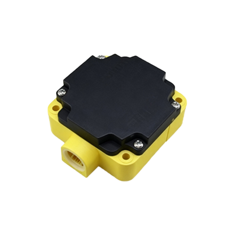
3. 4-Wire Sensors (Dual Output): These sensors provide both an NPN and a PNP output from the same unit. A clear, detailed diagram is essential to avoid mixing the two independent output circuits, showing separate common terminals or clearly labeled wires.
Key Elements in a High-Definition Wiring Diagram Image:
Terminal Designations: Labels like V+, V-, OUT, 0V, L+, L- must be legible.
Symbol Legend: Icons for power supply, sensor, load, and sometimes protective devices like diodes or fuses.
Wire Color Codes: Standardized (Brown, Blue, Black, White) but can vary; the diagram clarifies this.
Load Representation: Clearly shows what the sensor is controlling (PLC, relay, lamp).
Shielded Cable Connection: If applicable, shows proper grounding of the shield for noise immunity.
Best Practices for Using Wiring Diagrams:
1. Always Refer to the Datasheet: The specific sensor's datasheet contains the authoritative, model-specific wiring diagram. HD images from this source are mandatory.
2. Verify Supply Voltage: Match the sensor's voltage rating (e.g., 10-30VDC, 20-250VAC) exactly as shown in the diagram.
3. Check Output Configuration: Confirm NPN vs. PNP before connecting to your controller. Mismatching can lead to incorrect logic or damage.
4. Consider Load Compatibility: Ensure the sensor's output current rating suits the load's requirement. Diagrams often include notes on maximum load.
5. Implement Noise Reduction: For long cable runs or electrically noisy environments, follow diagram notes on using shielded cables and proper grounding.
In conclusion, a high-definition proximity sensor wiring diagram is not merely a reference image; it is a vital engineering document. Its clarity directly impacts installation accuracy and system robustness. By utilizing crisp, manufacturer-provided HD diagrams and adhering to the outlined wiring principles, electrical professionals can ensure seamless integration of proximity sensors, thereby enhancing the efficiency and safety of automated systems. Always prioritize diagram quality and specificity over generic guides to prevent costly errors and downtime.