In the realm of industrial automation, laser sensors are indispensable for precision detection, measurement, and control. Building a custom laser sensor can be a rewarding project for engineers seeking tailored solutions. This guide outlines the fundamental steps and considerations for constructing a reliable laser sensor system.
The core components include a laser diode, a photodetector (such as a photodiode or phototransistor), signal conditioning circuitry, and a microcontroller or dedicated processing unit. Begin by selecting an appropriate laser diode. For most industrial sensing applications, such as object detection or alignment, a visible red laser diode (e.g., 650 nm wavelength) with a low to medium power output (Class 2 or 3R, typically below 5 mW) is often suitable for safety and functionality. Ensure the diode is paired with a driver circuit to maintain stable current and prevent fluctuations that could affect performance.
The receiving end requires a photodetector sensitive to the laser's wavelength. A silicon photodiode is a common choice due to its fast response and good sensitivity in the visible to near-infrared spectrum. Position the detector to capture the reflected or interrupted laser beam. For diffuse reflection sensing, where the target scatters light, align the detector adjacent to the laser source. For through-beam sensing, place the detector directly opposite the laser, creating a path where an object interrupts the beam.
Signal conditioning is critical. The photodetector's output is typically a small current. Use a transimpedance amplifier (TIA) to convert this current into a measurable voltage. Design the TIA with careful attention to feedback resistor selection and bandwidth to minimize noise and ensure rapid response. Following amplification, a comparator circuit can be employed to generate a clean digital signal (high/low) when the received light intensity crosses a set threshold. This threshold adjusts sensitivity, allowing the sensor to ignore ambient light or background reflections.
Integrate a microcontroller (e.g., an Arduino, PIC, or ARM-based chip) for advanced processing. The microcontroller can read the digital output, implement timing functions for distance measurement via time-of-flight principles, or manage communication protocols like UART, I2C, or industrial fieldbuses. Programming should include debouncing algorithms to filter mechanical vibrations or electrical noise, ensuring stable output.
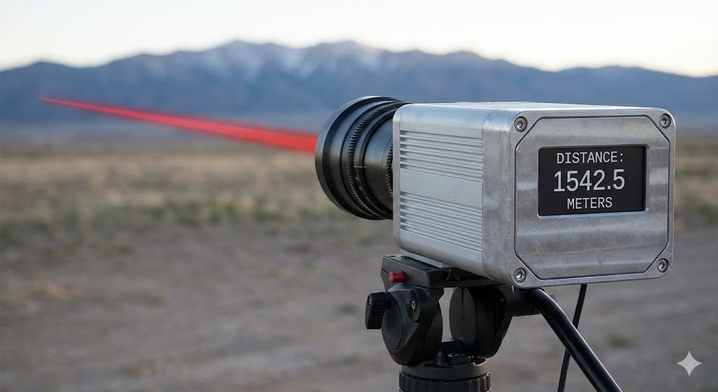
Enclosure and optics are vital for durability and accuracy. House the electronics in a robust, shielded metal or high-grade plastic enclosure to protect against electromagnetic interference (EMI), dust, and moisture per IP ratings relevant to the operating environment. Incorporate lenses or apertures to collimate the laser beam for a focused spot and to limit the detector's field of view, reducing stray light interference. Proper alignment during assembly is paramount; use adjustable mounts if necessary.
Finally, rigorous testing is essential. Calibrate the sensor against known distances or reflectivities. Verify its performance under varying ambient light conditions and with different target materials. Ensure compliance with laser safety standards (such as IEC 60825) by implementing necessary enclosures and labels.
Building a laser sensor requires a blend of optical, electronic, and programming expertise. While commercial sensors offer convenience, a custom-built unit provides flexibility for specific applications, from conveyor belt object counting to precise edge detection in manufacturing. Always prioritize safety, particularly when working with laser sources, to protect both the operator and the system's longevity.