In the realm of industrial automation, proximity sensors are indispensable workhorses. Their ability to detect the presence or absence of an object without physical contact makes them critical for counting, positioning, limit switching, and safety applications. However, their apparent simplicity can be deceptive. Even seasoned engineers and technicians can fall into subtle traps during sensor selection, installation, and configuration, leading to erratic performance, premature failure, or costly downtime. This article outlines common proximity sensor setup pitfalls and provides practical guidance to ensure robust and reliable operation.
One of the most fundamental yet frequently overlooked mistakes is the mismatch between sensor technology and the target material. Inductive sensors detect metals, but their sensing range varies significantly with the type of metal. A sensor calibrated for mild steel will have a drastically reduced range for aluminum, stainless steel, or copper. Assuming a universal sensing distance can lead to missed detections. Similarly, capacitive sensors react to a wide range of materials but are highly sensitive to environmental changes like humidity or dust accumulation on the face, causing false triggers. Photoelectric sensors, while versatile, face challenges with target color, reflectivity, and ambient light interference. The pitfall: selecting a sensor based solely on price or form factor without a thorough analysis of the target material and the operating environment.
Installation geometry is another critical area rife with errors. Proximity sensors, especially inductive ones, have a defined sensing field. Mounting them too close to each other can cause mutual interference, known as "crosstalk," where one sensor's electromagnetic field activates its neighbor. The standard rule is to maintain a minimum separation distance, often three times the sensor diameter for shielded (flush-mountable) types and more for unshielded types. Furthermore, the sensor face must be positioned correctly relative to the target's approach path. For reliable detection, the target should approach the sensor axially, not radially, to ensure it passes through the core of the sensing field. Parallel mounting or improper alignment can reduce the effective sensing distance and cause inconsistency.
Electrical wiring and load considerations are classic sources of trouble. Despite being a basic task, incorrect wiring remains a top cause of sensor failure. Key errors include: reversing polarity on DC sensors, applying AC power to a DC sensor (or vice versa), and neglecting to connect the load (e.g., a PLC input, relay, or indicator) in series. For 3-wire DC sensors, confusing the NPN (sinking) and PNP (sourcing) output types with the PLC input type will result in a non-functional circuit. Another subtle trap involves the load current. Operating a sensor for prolonged periods below its minimum rated load can lead to leakage current issues, causing the connected device to remain partially activated even when the sensor is off. Conversely, exceeding the maximum current rating will damage the output circuit. Always consult the datasheet and ensure compatibility with the power supply and the load.
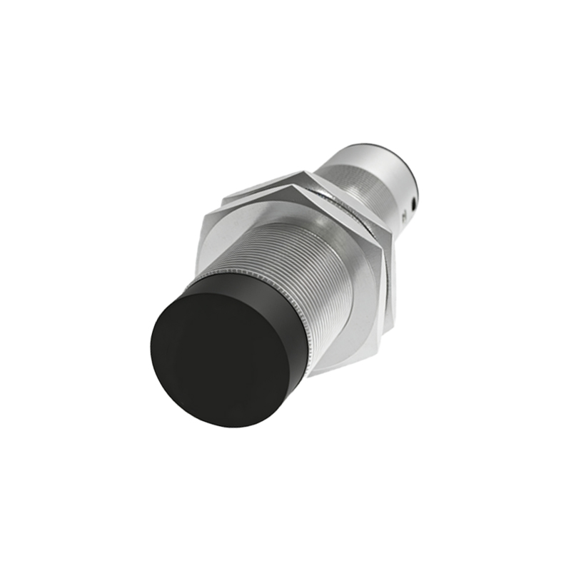
Environmental factors often create insidious problems that are difficult to diagnose. Excessive heat near ovens or welding stations can degrade sensor components and plastics. Chemical exposure from coolants, oils, or solvents can attack housing materials and seals. For inductive sensors, the presence of strong alternating magnetic fields from motors, transformers, or welding equipment can induce noise in the sensor or its cabling, leading to erratic switching. The pitfall here is installing a standard sensor in a harsh environment without specifying appropriate protection ratings (e.g., IP67 for dust and water ingress) or choosing a model designed for extreme temperatures or chemical resistance. Always consider the total environment, not just the immediate task.
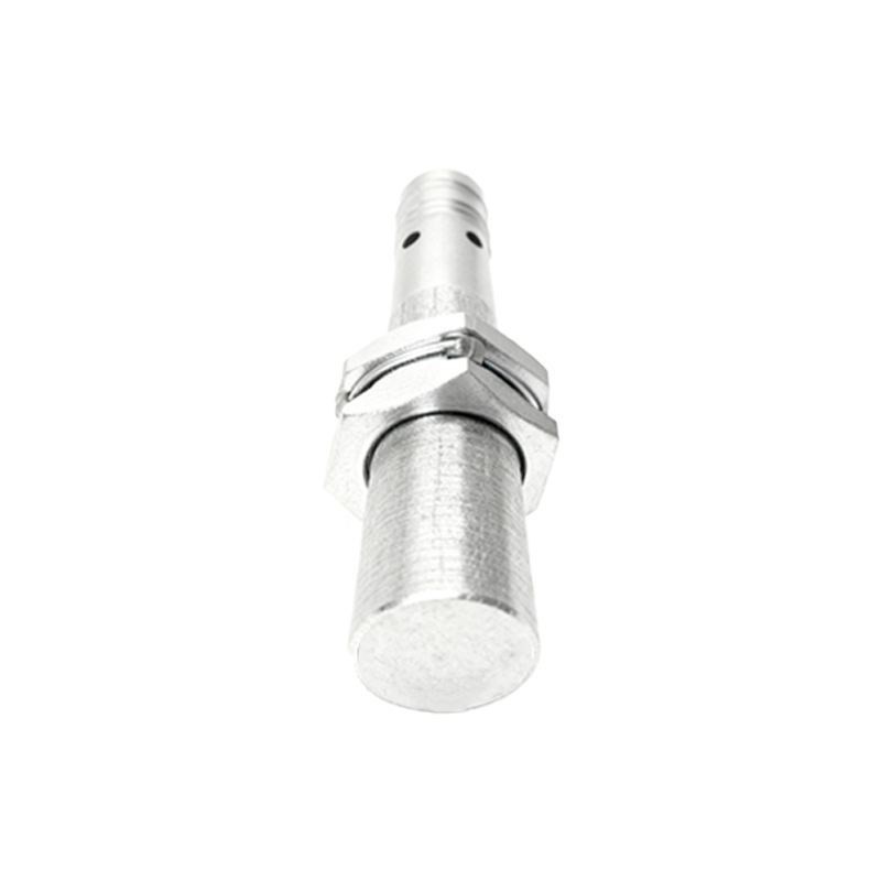
Finally, a lack of systematic commissioning and maintenance sets the stage for future failures. Assuming a newly installed sensor will work perfectly forever is a recipe for trouble. During startup, it is crucial to verify the actual sensing distance with the real target under real operating conditions—not just the theoretical value. Use the sensor's indicator LED cautiously; it shows the sensor's internal switching state, which may not always match the state at the load due to wiring faults. Establishing a regular inspection routine to check for physical damage, buildup of metallic swarf on inductive sensors, or grime on photoelectric lenses is essential. Vibration can loosen mounting hardware over time, gradually misaligning the sensor.
In conclusion, avoiding proximity sensor pitfalls requires a methodical approach that extends beyond simply mounting and connecting a device. It demands careful consideration of the target, the environment, the electrical system, and the mechanical installation. By understanding these common traps—material mismatch, improper installation, wiring errors, environmental oversights, and neglected maintenance—engineers can specify, install, and maintain proximity sensors that deliver the high reliability and longevity that modern automated systems depend on. Always prioritize the manufacturer's datasheet and application notes; they contain the specific details necessary to avoid these universal mistakes.