Proximity switch sensors are fundamental components in modern industrial automation and control systems. As an electrical engineer, understanding their correct wiring is paramount for ensuring system reliability, safety, and optimal performance. This guide provides a comprehensive overview of standard proximity sensor wiring diagrams, focusing on the prevalent 3-wire and 2-wire configurations, along with critical considerations for practical application.
The 3-wire DC proximity sensor is the most common type found in industrial settings. It typically features three distinct wires: brown, blue, and black. The brown wire is the positive supply line (+V), usually connected to a DC voltage source such as +24VDC. The blue wire is the negative supply line or common (0V), connected to the DC power supply's negative terminal. The black wire is the output signal line. In a sourcing (PNP) configuration, the black wire provides a positive voltage to the load (e.g., a PLC input) when the sensor is activated. Conversely, in a sinking (NPN) configuration, the black wire provides a path to ground (0V) for the load when activated. The load is always connected between the output wire (black) and the opposite potential (0V for PNP, +V for NPN). A detailed wiring diagram would show the power supply, the sensor with its three terminals, and the load device (like a PLC digital input module), clearly indicating the current path upon target detection.
For 2-wire AC/DC proximity sensors, wiring is simpler but requires careful load consideration. These sensors have only two wires, which are connected in series with the load and the power supply. They function like a switch. For AC models, they can be wired directly across an AC line (e.g., 120VAC) with the load. For DC models, polarity must be observed. A key specification is the leakage current; when the sensor is off, a small current still flows. The connected load must have a minimum current requirement (minimum load) below which the sensor may not switch off completely, potentially causing a "phantom signal" to the PLC. Engineers must verify that the PLC input's impedance is low enough to ensure the voltage drop across the off-state sensor is below the PLC's "OFF" threshold voltage.
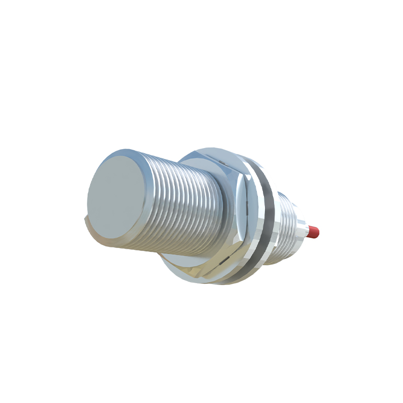
Shielded cables are highly recommended, especially in environments with significant electromagnetic interference (EMI) from motors, variable frequency drives (VFDs), or welding equipment. The cable shield should be grounded at only one end, typically at the control panel side, to prevent ground loops. Proper grounding of the sensor housing, if metallic, is also crucial. For DC sensors, always ensure a stable, regulated power supply. Voltage spikes or drops can cause erratic behavior. Fusing the supply line is a standard safety practice.
When interfacing with a Programmable Logic Controller (PLC), matching the sensor's output type to the PLC input type is essential. A PNP (sourcing) sensor is compatible with a sinking PLC input card, while an NPN (sinking) sensor pairs with a sourcing PLC input card. Mismatching can lead to non-operation. Always consult both the sensor datasheet and the PLC hardware manual. For diagnostic purposes, many sensors feature an LED indicator that lights when an object is within the sensing range. This LED is an invaluable tool for troubleshooting wiring or alignment issues.
In complex systems with multiple sensors, careful planning of the wiring layout is necessary. Use separate conduits for power and signal cables where possible to reduce noise coupling. For long cable runs, consider the voltage drop; using a thicker gauge wire may be necessary to ensure the sensor receives adequate voltage. For sensors in hazardous locations, ensure the wiring and installation comply with the appropriate protection standards (e.g., explosion-proof enclosures, intrinsic safety barriers).
In summary, a correct proximity sensor wiring diagram is more than just connecting wires. It involves selecting the right sensor type (AC/DC, 2-wire/3-wire, PNP/NPN), understanding the load characteristics, implementing noise suppression techniques, and ensuring compatibility with the control system. By adhering to the manufacturer's diagrams and incorporating these engineering principles, you can build robust, fault-resistant automation systems. Always perform a systematic check: verify power, check the indicator LED, and measure the output signal with a multimeter or oscilloscope before integrating the sensor into the live control loop.