In industrial automation and control systems, proximity sensors play a crucial role in detecting the presence or absence of objects without physical contact. Among various configurations, the 2-wire proximity sensor is widely favored for its simplicity and cost-effectiveness. This article provides a comprehensive guide to the wiring diagram, working principle, installation considerations, and troubleshooting tips for 2-wire proximity sensors.
A 2-wire proximity sensor operates with just two wires: one for power supply and the other for the signal output. Unlike 3-wire or 4-wire sensors, it does not have a separate ground wire. Instead, the sensor uses the same two wires to complete the circuit for both power and switching functions. The wiring diagram typically shows one wire connected to the positive terminal of the DC power supply (usually labeled as brown or black), and the other wire connected to the load (such as a PLC input, relay, or indicator). The load is then connected back to the negative terminal of the power supply, forming a closed loop. This design simplifies installation and reduces wiring costs, making it ideal for applications with space constraints or budget limitations.
The working principle of a 2-wire proximity sensor is based on its ability to act as a switch in the circuit. When no target is detected, the sensor remains in a high-impedance state, allowing a small leakage current to flow (typically less than 2 mA). This leakage current is insufficient to activate the load, keeping it in the "off" state. When a target enters the sensing range, the sensor switches to a low-impedance state, allowing sufficient current to flow through the load and activate it. The sensor's output is often described as "normally open" (NO) or "normally closed" (NC), depending on the default state. For example, in a NO configuration, the sensor closes the circuit when a target is detected, while in an NC configuration, it opens the circuit.
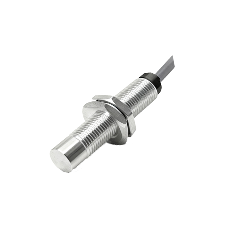
When installing a 2-wire proximity sensor, several key factors must be considered to ensure reliable operation. First, select the appropriate power supply voltage, which typically ranges from 10 to 30 VDC for most models. Exceeding the voltage rating can damage the sensor, while insufficient voltage may cause malfunction. Second, pay attention to the load current requirements. The sensor must handle the current drawn by the load, including inrush currents from devices like relays or solenoids. A common mistake is overlooking the leakage current, which can inadvertently activate sensitive loads. To prevent this, use a load with a minimum operating current higher than the sensor's leakage current, or add a bypass resistor in parallel with the load. Third, ensure proper mounting and alignment. Metallic objects or other sensors nearby can interfere with the sensing field, leading to false triggers. Maintain a clearance distance as specified in the datasheet, usually at least twice the sensor's diameter.
Wiring a 2-wire proximity sensor involves straightforward steps. Begin by disconnecting the power supply to avoid electrical hazards. Identify the sensor wires: the brown wire (or sometimes black) is for positive power, and the blue wire (or white) is for the load connection. Connect the brown wire to the positive terminal of the DC power source. Connect the blue wire to one terminal of the load. Then, connect the other terminal of the load to the negative terminal of the power supply. Double-check all connections for tightness and correct polarity. Once wired, restore power and test the sensor by bringing a target within its sensing range. The load should activate accordingly. If using an inductive proximity sensor (common for metal detection), ensure the target material is compatible—ferrous metals like iron yield the longest sensing distances, while non-ferrous metals like aluminum may require adjustment.
Troubleshooting common issues with 2-wire proximity sensors often revolves around electrical characteristics. If the sensor fails to activate the load, verify the power supply voltage and current capacity. Measure the voltage at the sensor terminals under load to rule out voltage drops. Check for loose connections or damaged wires. If the load remains activated when no target is present, the leakage current might be too high. In such cases, increase the load's minimum current or install a shunt resistor. Environmental factors like temperature extremes, moisture, or vibration can also affect performance. Choose sensors with appropriate IP ratings for harsh conditions. For noise immunity in electrically noisy environments, use shielded cables and keep sensor wires away from high-voltage lines.
In summary, 2-wire proximity sensors offer a streamlined solution for object detection in industrial settings. Their simple wiring diagram reduces complexity, while proper installation and maintenance ensure longevity and accuracy. By understanding the wiring principles, load considerations, and potential pitfalls, engineers can effectively integrate these sensors into control systems for applications ranging from conveyor belts to robotic arms. Always refer to the