Proximity sensors are indispensable components in modern industrial automation, providing non-contact detection of objects for positioning, counting, and safety applications. Proper calibration and debugging are critical to ensure reliable operation, minimize false triggers, and extend sensor lifespan. This tutorial outlines a systematic approach for engineers and technicians.
1. Pre-Installation Checks & Selection Verification
Before physical installation, verify the sensor's specifications match the application requirements. Key parameters include:
Sensing Type: Inductive (for metals), capacitive (for non-metals, liquids), or ultrasonic (for distance).
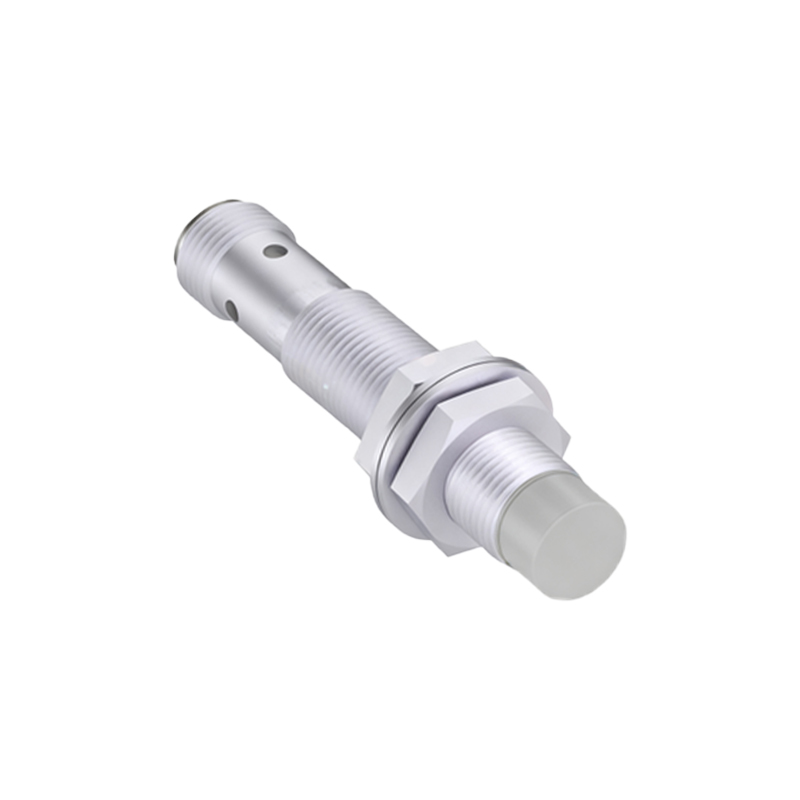
Sensing Distance (Sn): The nominal operating distance. Ensure the target object will be within this range. Remember, the effective sensing distance can be reduced when installing in metal flush mounts.
Output Type: NPN (sinking) or PNP (sourcing) DC, or NO/NC (Normally Open/Normally Closed) configurations. Confirm compatibility with your PLC or controller input card.
Electrical Characteristics: Operating voltage (e.g., 10-30V DC) and current rating.
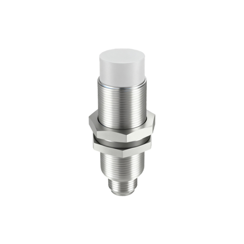
Environmental Ratings: IP rating for dust/water resistance and temperature range suitability for the operating environment.
2. Mechanical Installation and Alignment
Correct mechanical setup is foundational.
Mounting: Secure the sensor firmly to minimize vibration. For inductive sensors, maintain the recommended clearance around the sensing face (typically 1-2 times the sensor diameter) from surrounding metal to prevent interference.
Alignment: Precisely align the sensing face perpendicular to the target's approach path. Misalignment can significantly reduce the effective sensing distance.
Target Considerations: For inductive sensors, the target material (steel, aluminum, copper) and size affect performance. The target should be at least as large as the sensor's sensing face. For standard sensing distances, use a mild steel target of recommended thickness.
3. Electrical Wiring and Connection
Always follow the manufacturer's wiring diagram. General steps:
Power Down: Ensure the circuit is de-energized before connecting wires.
Wire Connections: Connect the Brown wire (+V), Blue wire (0V/Common) for DC sensors. Connect the Black (or White) output wire to your controller's input. For 3-wire sensors, ensure correct NPN/PNP wiring to the PLC's sinking/sourcing input.
Load Connection: Connect the load (relay, PLC input, lamp) in series with the output. For DC sensors, always include a protective flyback diode for inductive loads like relays.
Shielding: In electrically noisy environments, use shielded cables and ground the shield at one end only (usually the control panel end).
4. Calibration and Sensitivity Adjustment
Many proximity sensors feature a potentiometer or teach-in function for fine-tuning.
Power On: Apply the correct operating voltage.
Initial Test: Introduce the target object to the sensing face. Observe the sensor's indicator LED (if present).
Adjustment: Using a non-metallic tool, slowly adjust the sensitivity potentiometer.
Turn clockwise (usually) to increase sensitivity/longer range. This is useful for detecting smaller or non-ferrous metals (aluminum).
Turn counter-clockwise to decrease sensitivity/shorter range. This helps in ignoring nearby non-target objects or mitigating effects from background materials (for capacitive sensors) or electrical noise.
Method: Bring the standard target to the desired operating distance. Adjust the potentiometer until the output just switches state (LED lights). Then, slightly decrease the sensitivity (turn back 5-10%) to provide a safety margin against drift. For applications with varying targets, test with the smallest and largest expected target.
5. Systematic Debugging for Common Issues
If the sensor malfunctions, follow this logical debugging sequence:
Issue: No Output / No Indicator LED.
Debug: Check power supply voltage at the sensor terminals with a multimeter. Verify wiring polarity. Check for broken wires or loose connections. Ensure the load impedance is not too high.
Issue: Output Stuck ON or OFF.
Debug: Disconnect the output wire from the controller. Measure output voltage/state directly. If still incorrect, the sensor may be faulty. If correct, the issue may be in the controller wiring or input circuit.
Issue: Intermittent Operation or False Triggering.
Debug: This is often environmental. Check for:
1. Electrical Noise: Ensure proper grounding, separation from high-voltage cables, and use of shielded cables.
2. Physical Interference: Check for vibration, loose