In industrial automation and control systems, proximity sensors are ubiquitous components, providing non-contact detection of metallic or, in some cases, non-metallic objects. A common question that arises in panel design and field troubleshooting is whether these sensors, particularly the ubiquitous two-wire DC variety, can be connected in series. The short answer is yes, but with significant caveats and a thorough understanding of the underlying electrical principles. This article delves into the practicalities, calculations, and critical considerations for successfully implementing a series connection of two-wire proximity switches.
First, it is essential to understand the fundamental operating principle of a two-wire DC proximity sensor. Unlike their three-wire counterparts which have separate power, ground, and signal lines, a two-wire sensor operates in series with the load (typically a PLC input or a relay coil). It functions by modulating its internal impedance. In its normal state (no target detected), the sensor presents a high impedance, allowing only a small leakage current (often termed standby current) to flow, insufficient to activate the load. When a target enters its sensing range, the sensor switches to a low-impedance state, allowing the full circuit current to flow, thereby energizing the load. This behavior is analogous to a switch, but with inherent voltage drops and current consumption.
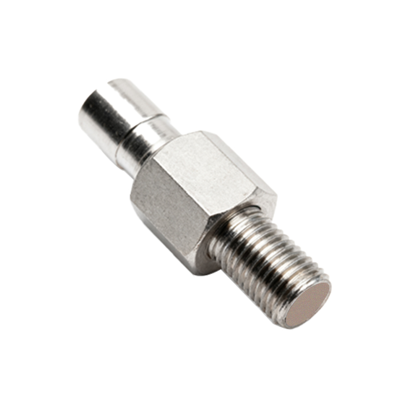
The core challenge of connecting sensors in series stems from their voltage drop characteristics. Each active (target detected) two-wire sensor has a residual voltage drop across its terminals, typically ranging from 1.5V to 5V, depending on the model and current. When sensors are connected in series, their voltage drops are additive. For the load to be energized, the supply voltage must be high enough to overcome the sum of all sensor voltage drops and still provide sufficient voltage at the load terminals to meet its minimum operating requirement.
Let's consider a practical example. Suppose we have three 24V DC two-wire sensors, each with a voltage drop (V_drop) of 3V when active. The load is a PLC digital input with a minimum turn-on voltage of 15V. If all three sensors are activated simultaneously, the total voltage drop across the sensors is 9V (3V 3). Therefore, the voltage available for the PLC input is 24V - 9V = 15V. This is precisely at the minimum threshold, leaving no margin for error. Any variance in supply voltage, sensor characteristics, or cable resistance could prevent reliable operation. This calculation is the first and most crucial step: V_supply - (Σ V_drop_sensors) >= V_load_min.
Current is another critical factor. The circuit current is determined by the load. All series-connected sensors and the load share the same current. You must verify that the maximum current rating of each sensor is not exceeded by the load's operating current. Furthermore, the leakage current of inactive sensors becomes a potential pitfall. In a series circuit, if one sensor is inactive (high impedance state), its leakage current is the only current flowing in the entire loop. This tiny current, usually a few milliamps, is almost certainly below the minimum holding current of a relay or the turn-on threshold of a PLC input, causing the load to de-energize. Therefore, for a series connection to work logically as an AND function (all sensors must detect a target to activate the load), all sensors must be active simultaneously. If the requirement is for an OR function (any sensor can activate the load), a parallel connection is mandatory.
Wiring and diagnostics also present challenges. A fault in any single sensor (e.g., a short circuit or an open circuit) will disrupt the entire series string, making troubleshooting more complex than with individually wired sensors. Proper labeling and strategic test point placement are highly recommended.
Best Practices and Recommendations:
1. Consult Datasheets: Always obtain the specific voltage drop (at rated current), leakage current, and current ratings from the manufacturers' datasheets for all components.
2. Design with Margin: Apply a safety margin of at least 20% in your voltage calculation. For critical applications, consider using a higher supply voltage (e.g., 30V for a 24V system) if the load permits.
3. Consider Alternatives: Before opting for a series connection, evaluate if using three-wire sensors (with their outputs wired in series) or a small logic module/PLC is more reliable and maintainable. Three-wire sensors with PNP outputs, for instance, can be easily wired in series to a common input, often with more predictable logic.