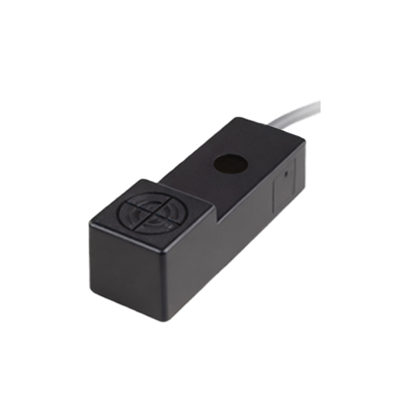
In the realm of industrial automation and control systems, photoelectric proximity sensors are indispensable components for non-contact detection of objects. Their operation hinges on the principles of light emission and reception, enabling precise sensing across various environments. This article delves into the schematic diagram of a typical photoelectric proximity sensor, elucidating its core components and operational workflow to provide a comprehensive understanding for engineers and technicians.
At the heart of a photoelectric proximity sensor lies its optical system, comprising a light emitter and a receiver. The emitter, typically an infrared LED (Light Emitting Diode), generates a modulated light beam directed toward the target area. Modulation is crucial to minimize interference from ambient light, ensuring reliable detection. The receiver, often a phototransistor or photodiode, captures the reflected or transmitted light, converting it into an electrical signal. The schematic diagram illustrates these elements connected to an integrated circuit (IC) that manages signal processing and output control.
The schematic begins with the power supply section, where external DC voltage (commonly 10-30 VDC) is regulated to provide stable operating conditions for the sensor's internal components. A voltage regulator IC ensures consistent power to the emitter and receiver circuits, preventing fluctuations that could lead to false triggers. The emitter circuit includes a current-limiting resistor in series with the LED to protect it from overcurrent, while a modulation oscillator drives the LED at a specific frequency (e.g., several kilohertz). This modulated signal is key to distinguishing the sensor's light from external sources.
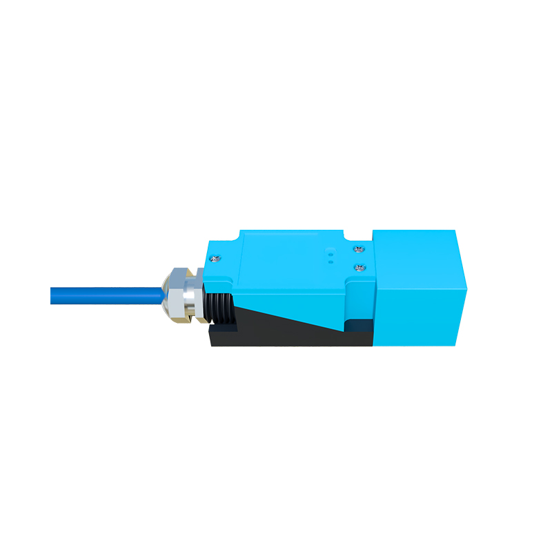
In the receiver circuit, the phototransistor is biased to operate in its linear region, allowing it to respond to variations in light intensity. When an object enters the sensing range, it reflects or interrupts the light beam, altering the amount of light reaching the receiver. This change modulates the phototransistor's output current, which is then amplified by an operational amplifier (op-amp) stage. The amplified signal is fed into a demodulator circuit that filters out noise and extracts the original modulation frequency, enhancing signal integrity.
The processed signal is compared against a threshold set by a potentiometer or digital trimmer in the schematic, enabling adjustment of the sensing distance or sensitivity. If the signal exceeds the threshold, a comparator triggers the output stage, which may consist of a transistor switch (for NPN or PNP outputs) or a solid-state relay. The output interfaces with external devices like PLCs (Programmable Logic Controllers) or actuators, providing a digital signal (ON/OFF) indicative of object presence. The schematic often includes protective elements such as diodes for reverse polarity protection and capacitors for noise suppression.
A critical aspect depicted in the schematic is the sensor's configuration type: diffuse, retro-reflective, or through-beam. In diffuse models, the emitter and receiver are housed together, relying on light reflection from the target. Retro-reflective types use a separate reflector to bounce light back to the receiver, while through-beam sensors have separate emitter and receiver units for direct beam transmission. The schematic varies slightly for each type, with additional components like polarization filters in retro-reflective sensors to avoid false signals from shiny objects.
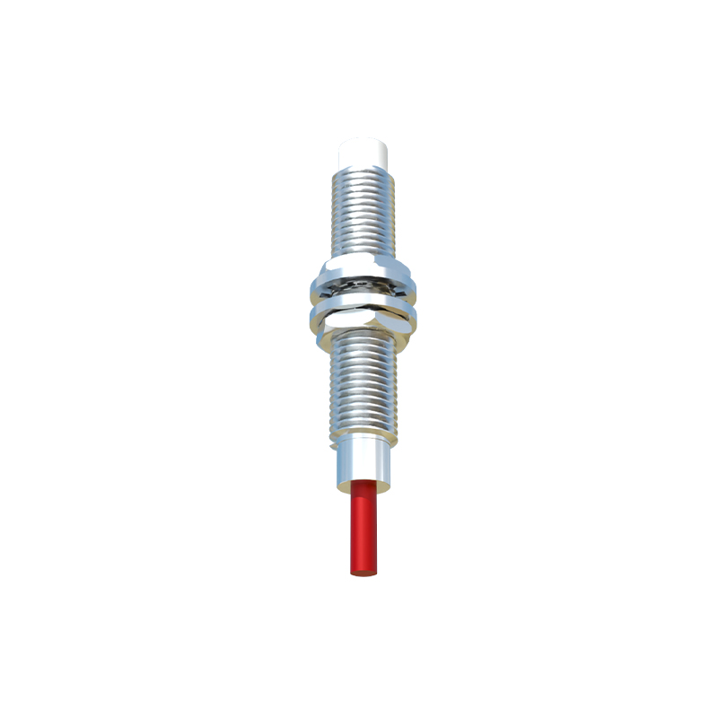
Understanding the schematic diagram empowers engineers to troubleshoot issues, such as incorrect wiring or component failure, and optimize sensor performance. For instance, adjusting the potentiometer can fine-tune sensitivity for different surface colors or materials, while proper grounding in the schematic minimizes electromagnetic interference. In summary, the photoelectric proximity sensor schematic serves as a blueprint for its reliable operation, blending optical and electronic principles to achieve efficient, non-contact detection in diverse industrial applications.