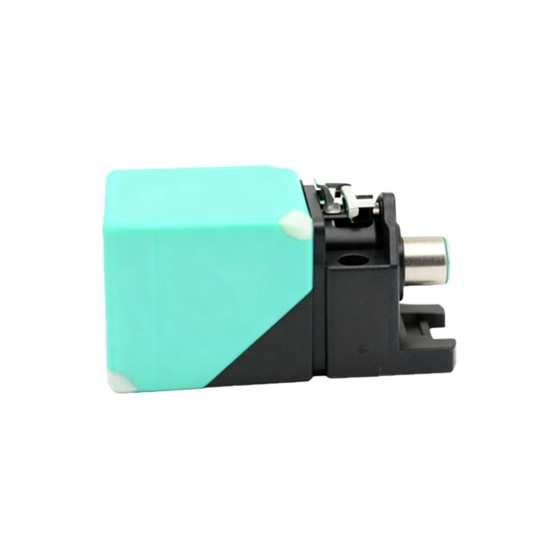
Mechanical proximity sensors are fundamental components in industrial automation, offering reliable object detection without physical contact. These devices operate based on the principle of mechanical actuation triggered by the presence of an object within a specified range. Typically, they consist of a movable actuator, such as a lever or plunger, which is physically displaced when an object approaches. This displacement engages an internal switching mechanism—often a set of electrical contacts—that changes state to signal detection. The simplicity of their design ensures durability in harsh environments, making them ideal for applications in manufacturing, packaging, and material handling.
A key aspect of mechanical proximity sensors is their reliance on direct mechanical force. Unlike inductive or capacitive sensors that use electromagnetic fields, these sensors require physical interaction with the target. The actuator moves in response to contact, which then activates the switch. This mechanism is often visualized in diagrams showing the actuator's movement, spring return system, and contact arrangement. For instance, a common diagram depicts a lever-type actuator pivoting to close normally open (NO) contacts, completing an electrical circuit. Another variant, the plunger-style sensor, shows a linear motion compressing a spring to toggle the switch. These illustrations help engineers understand the sensor's operation, including critical parameters like actuation force, travel distance, and reset behavior.
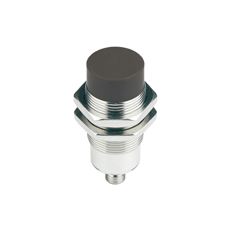
The internal switching mechanism can vary, with options including snap-action switches for quick response or slow-break switches for reduced arcing. Diagrams often highlight the contact materials, such as silver or gold plating, which influence longevity and conductivity. Additionally, mechanical proximity sensors may incorporate seals or housings rated for IP67 or higher, protecting against dust and moisture. In applications, they are commonly used for limit sensing in conveyor systems, position verification in assembly lines, or safety interlocks in machinery. Their robustness allows them to withstand vibrations, shocks, and temperature fluctuations, though regular maintenance is advised to prevent wear on moving parts.
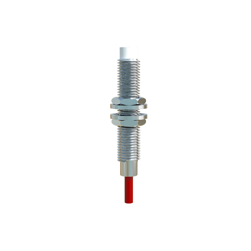
To optimize performance, selection criteria include actuator type, switch rating, and environmental compatibility. For example, roller lever actuators suit high-speed detection, while whisker actuators detect fragile objects. Diagrams aid in visualizing these configurations, showing how actuator geometry affects sensing angles and ranges. Furthermore, wiring schematics often accompany principle diagrams, illustrating connections to control systems like PLCs. By studying these images, technicians can troubleshoot issues like false triggers or failure to actuate, ensuring minimal downtime in automated processes.
In summary, mechanical proximity sensors provide a cost-effective and reliable solution for object detection through straightforward mechanical principles. Detailed diagrams enhance comprehension of their operation, from actuator movement to electrical output, supporting effective integration in diverse industrial settings. As automation evolves, these sensors remain integral due to their simplicity and adaptability, with ongoing innovations focusing on enhanced materials and miniaturization for specialized applications.