Proximity sensors are indispensable components in modern industrial automation, robotics, and countless electronic devices. Their ability to detect the presence or absence of an object without physical contact offers unparalleled reliability and longevity. While the underlying sensing technologies—inductive, capacitive, ultrasonic, and photoelectric—vary, their operation hinges on well-defined electronic circuit principles. This article delves into the fundamental circuit architectures that bring these sensors to life, focusing on the ubiquitous inductive and capacitive types.
At the heart of an inductive proximity sensor lies an LC oscillator circuit. The "L" represents a coil of wire wound around a ferrite core, which constitutes the sensor's active face. This coil forms the inductive element. The "C" represents a capacitor, typically integrated into the circuit. Together, they form a tuned tank circuit designed to oscillate at a specific high frequency, often in the range of 100 kHz to 1 MHz. When powered, this circuit generates a high-frequency electromagnetic field emanating from the coil. In the absence of a metallic target, the oscillator runs freely at its resonant frequency, producing a stable sinusoidal signal.
The critical detection mechanism involves eddy currents. When a conductive (typically ferrous or non-ferrous metal) target enters this oscillating electromagnetic field, eddy currents are induced on the target's surface. According to Lenz's Law, these currents create their own opposing magnetic field, which interacts with the sensor's field. This interaction effectively loads the oscillator, increasing the energy loss ("damping") in the LC tank circuit. This damping causes a measurable decrease in the amplitude of the oscillation. A subsequent evaluation circuit, often a Schmitt trigger or a comparator, continuously monitors this amplitude. Once the amplitude drops below a predefined threshold—indicating a target within the specified sensing range—the evaluation circuit triggers a state change. This change drives a solid-state output switch (usually an NPN or PNP transistor) to change its conduction state, thereby providing a digital ON/OFF signal to the controller (PLC, microcontroller, etc.).
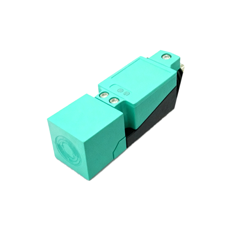
The capacitive proximity sensor shares a similar circuit philosophy but operates on a different physical principle: the change in capacitance. Its sensing element consists of two conductive electrodes arranged as open capacitor plates, often forming a single, front-facing sensor surface. These electrodes are connected to an RC or another oscillator circuit. The sensor and the ground (or earth) form one capacitor (C_sensor). The circuit is adjusted to oscillate in a stable state with this inherent capacitance.
When any object, metallic or non-metallic (like plastic, wood, or liquid), approaches the sensor face, it alters the dielectric properties of the space between the electrodes. The object, especially if conductive, effectively becomes part of the dielectric, increasing the overall capacitance (C_sensor increases). In the case of non-conductive materials, their dielectric constant (ε_r) replaces that of air, also leading to a capacitance increase. This change in capacitance directly affects the oscillator's behavior. Just like in the inductive sensor, the increased capacitance alters the oscillation characteristics, typically reducing the frequency or amplitude. A dedicated evaluation circuit detects this shift. When the change surpasses a sensitivity-adjusted threshold, the circuit activates the output switch.
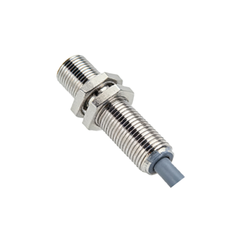
Beyond the core oscillator and evaluator, modern proximity sensor circuits incorporate several key stages for robustness and functionality. A voltage regulator ensures stable operation despite fluctuations in the supply voltage (commonly 10-30V DC). Output protection circuits, including flyback diodes for inductive loads and current-limiting resistors, safeguard the switching transistor from voltage spikes and overloads. LED indicators are driven in parallel to the output to provide visual status confirmation. Some advanced sensors feature short-circuit and reverse-polarity protection, embedding additional diodes and fusing elements directly into the circuit.
Understanding these circuit principles is crucial for proper sensor selection and troubleshooting. For instance, knowing that inductive sensors react only to metals informs their use in metal detection applications, while capacitive sensors are ideal for level detection of fluids or granulates. The sensing range is directly influenced by the oscillator's power and the evaluator's threshold setting. Interference from adjacent sensors or large metal structures can be understood as unwanted coupling into the LC tank or capacitive field, necessitating proper mounting distances.
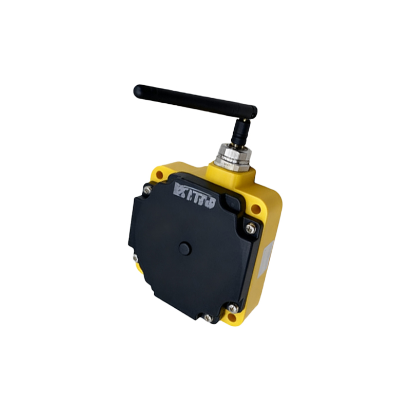
In summary, the magic of contactless detection is grounded in elegant electronic circuits. From the oscillating electromagnetic field of an inductive sensor's LC tank to the shifting capacitance field in a capacitive sensor, the core principle remains: a physical interaction modulates an electrical signal, which is precisely evaluated to provide a clean, reliable switch signal. This seamless translation of a physical presence into an electrical command is what makes the proximity sensor a cornerstone of automated systems.