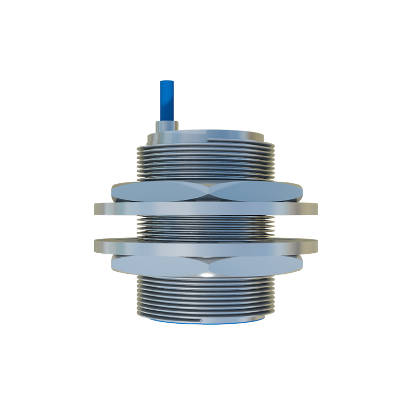
In the realm of industrial automation and control systems, proximity sensors are indispensable components. For engineers, technicians, and procurement specialists, accurately identifying and selecting the right sensor often begins with its model picture. A proximity sensor model picture is far more than a simple photograph; it is a critical visual document packed with technical and physical information essential for integration, maintenance, and sourcing.
A standard model picture typically provides a clear, high-resolution view of the sensor from multiple angles, often including front, side, and rear perspectives. The primary purpose is to convey the physical form factor, which is paramount for mechanical integration. Key dimensional characteristics visible include the sensor's housing shape—whether it's cylindrical (e.g., M8, M12, M18, M30 threaded barrels), rectangular, or cubic. The picture allows one to discern the mounting style: threaded barrel for easy installation in a drilled hole, flat-pack with mounting holes, or a specialized bracket-mount design. The material of the housing, often indicated by its finish (e.g., nickel-plated brass, stainless steel, or PBT plastic), is also visually apparent, hinting at its IP rating and suitability for harsh environments like washdown areas or foundries.
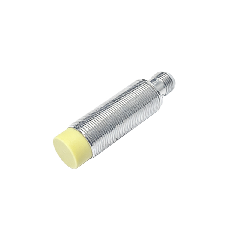
Crucially, the model picture highlights the sensing face. For inductive sensors (detecting metals), this face is typically flat. For capacitive sensors (detecting liquids, powders, or non-metals), the sensing area might be differently designed. The picture often shows if the sensor is shielded (flush-mountable) or unshielded (non-flush), a detail critical for installation adjacent to metal surfaces. The connection method is another vital element clearly displayed: a fixed cable with specified length and jacket color (often PUR or PVC), or a quick-disconnect connector (like M8 or M12 3-pin, 4-pin). The connector's gender and coding (A-coded, B-coded) are usually visible, preventing wiring errors.
Beyond basic form, detailed model pictures include close-ups of the labeling and markings on the sensor body. This is where the model number, serial number, brand logo, electrical specifications (voltage range: e.g., 10-30V DC, 20-250V AC), output type symbol (PNP/NPN, NO/NC), and certification marks (CE, UL, ATEX for hazardous areas) are located. A clear picture enables accurate reading of this alphanumeric code, which is the direct key to the sensor's datasheet and technical specifications.
Understanding these pictures is essential for several practical scenarios. During system design, engineers compare model pictures from catalogs to ensure the sensor fits the allocated space and mounting setup. For maintenance and replacement, a technician can use a picture from a legacy system or a damaged unit to identify an exact or functional equivalent, matching the form factor and connection to avoid costly machine modifications. In procurement, providing a model picture to a supplier drastically reduces the risk of ordering an incorrect variant, especially when model numbers are long and complex with subtle suffixes indicating connection type or output configuration.
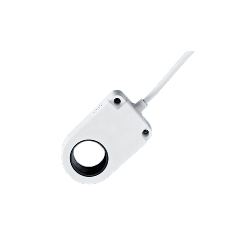
However, reliance solely on a picture has limitations. A picture cannot convey dynamic performance parameters like sensing distance, repeat accuracy, switching frequency, or hysteresis. It does not specify the exact sensing technology (inductive, capacitive, ultrasonic, magnetic). Therefore, the model picture must always be cross-referenced with the official datasheet using the visible model number. The datasheet provides the complete electrical, performance, and environmental specifications that the image cannot.
In conclusion, a proximity sensor model picture serves as a fundamental visual interface between the physical device and the technical documentation. It bridges the gap between a part number on a list and the tangible component on the factory floor. For professionals in the electrical and automation fields, developing the skill to interpret these images—extracting details on size, mount, connection, and markings—is a practical necessity. It streamlines design, ensures correct installation, facilitates efficient troubleshooting, and guarantees accurate part replacement, ultimately contributing to system reliability and operational uptime. Always remember to use the picture as the starting point for identification, and complete the process by consulting the full technical specifications for a successful application.