In industrial automation and machinery control, dual proximity sensors are frequently employed to enhance reliability, provide redundancy, or enable more complex positional detection. Proper wiring is fundamental to ensuring these sensors function correctly, safely, and in harmony with the control system. This guide provides a detailed, professional approach to wiring dual proximity sensors, covering common configurations, best practices, and critical considerations.
First, it is essential to identify the sensor type and specifications. Proximity sensors are broadly categorized by their output type and sensing technology. The two most common output types are PNP (sourcing) and NPN (sinking). PNP sensors switch the positive voltage to the load, while NNP sensors switch the negative or ground connection. Mismatching these with your PLC (Programmable Logic Controller) or relay input can lead to malfunction or damage. Always consult the sensor datasheet for voltage ratings (typically 10-30V DC), current capacity, output function (normally open/NO or normally closed/NC), and whether they are 2-wire, 3-wire, or 4-wire devices. For dual-sensor setups, the sensors are often identical in type and rating.
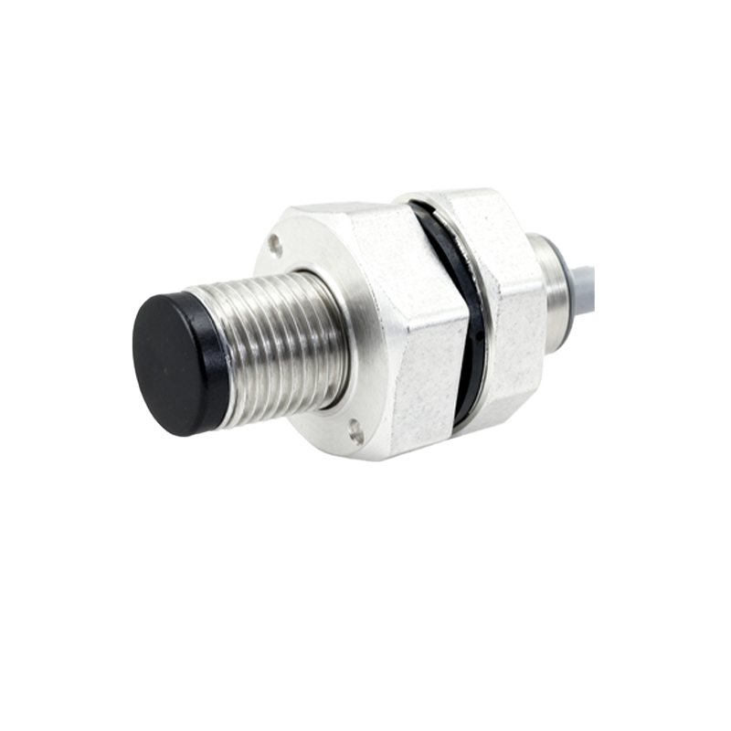
The most straightforward application is wiring two independent sensors to separate controller inputs. This is typical for redundancy or monitoring two distinct positions on a machine. For a 3-wire DC sensor, the wiring procedure is as follows:
1. Power Supply Connection: Connect the positive terminal of your DC power supply (e.g., 24V) to the brown (or red) wire of both sensors. Connect the negative terminal of the power supply to the blue (or black) wire of both sensors. This provides a common power bus.
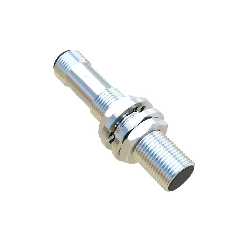
2. Output Signal Connection: Connect the black (or white) output wire of Sensor A to a designated input channel on your PLC (e.g., I0.0). Connect the output wire of Sensor B to a separate PLC input (e.g., I0.1). Each sensor's signal is now independent.
3. Load Consideration: Ensure the PLC input module is compatible (sinking for PNP, sourcing for NPN). If using relays, connect the sensor output to the relay coil, with the coil's other terminal connected to the opposite power rail.
A more advanced configuration involves wiring two sensors in series or parallel to create a logical AND or OR function at a single input point. This saves controller inputs but requires careful planning.
Series Connection (Logical AND): Wire the output wires of both sensors in series before connecting to the single PLC input. For this to work, both sensors must be of the same type (e.g., both PNP NO). The input will only receive voltage (signaling TRUE) when both Sensor A AND Sensor B are activated. This is useful for safety interlocks where two conditions must be met simultaneously.
Parallel Connection (Logical OR): Wire the output wires of both sensors in parallel, then connect the common node to the PLC input. With PNP NO sensors, the input will receive voltage (TRUE) if either Sensor A OR Sensor B is activated. This is useful for monitoring multiple potential trigger points.
Shielding and noise immunity are paramount, especially in environments with variable frequency drives (VFDs), motors, or welding equipment. Always use shielded cable for sensor connections. Connect the cable shield to a functional earth ground at the control panel end only, typically via a cable gland or DIN-rail mounted grounding clip. Do not connect the shield at both ends to avoid ground loops. Keep sensor cables separate from high-voltage power lines; cross them at 90-degree angles if necessary.
For long cable runs, consider voltage drop. Calculate the resistance of your cable and ensure the voltage at the sensor remains within its operating range. Using a higher gauge (thicker) wire can mitigate this issue. Additionally, always implement proper circuit protection. A fuse (1-2A, slow-blow) on the positive supply line to the sensor group is recommended. For outputs, check if your PLC input module has internal protection or requires external resistors.
Finally, thorough testing is non-negotiable. Before integrating into the full system, test each sensor individually with its intended target. Use a multimeter to verify output voltage states (active vs. inactive). Then, test the logical function (AND/OR) if wired in series/parallel. Observe the behavior in the control program to confirm the input triggers match the physical sensor state.
In summary, wiring dual proximity sensors demands attention to electrical compatibility, logical intent, and environmental robustness. By methodically selecting components, following correct wiring diagrams, implementing noise suppression, and conducting rigorous testing, engineers can ensure a reliable and maintainable sensor system that meets the rigorous demands of industrial automation.
SEO关键词