In the realm of industrial automation and machine safety, proximity sensors are indispensable components. Their primary function is to detect the presence or absence of an object without physical contact, triggering a corresponding output signal. However, the efficacy of these sensors is not solely dependent on their intrinsic quality or type (inductive, capacitive, ultrasonic, or photoelectric). Arguably, one of the most critical factors determining their reliability, accuracy, and longevity is their physical placement. Incorrect installation can lead to false triggers, missed detections, premature failure, and even safety hazards. This article delves into the key considerations and best practices for determining the optimal location for proximity sensors in various industrial settings.
The fundamental principle guiding sensor placement is ensuring a reliable detection zone. Every proximity sensor has a specified nominal sensing distance (Sn). This is the ideal operating distance under standardized conditions. In real-world applications, effective placement requires accounting for several environmental and operational factors that can influence this distance. First and foremost, the sensor must be positioned within the actual sensing range of the target object. This seems obvious, but it requires precise mechanical alignment. For instance, an inductive sensor designed to detect a metal flag on a rotating shaft must be mounted so that the flag passes squarely through the sensor's active face at a distance less than Sn. Misalignment can cause inconsistent or failed detection.
Environmental interference is a paramount concern. For inductive sensors, which detect metallic objects, placement must avoid proximity to other large metal structures, motors, or power cables that could generate electromagnetic fields and cause erratic behavior. A general rule is to maintain a minimum distance of three times the sensor diameter from such interfering objects. Similarly, capacitive sensors, sensitive to material density and moisture, should be installed away from sources of humidity, dust accumulation, or varying material backgrounds. Photoelectric sensors require a clear line of sight, free from obstructions, fog, oil mist, or ambient light sources that could saturate the receiver.
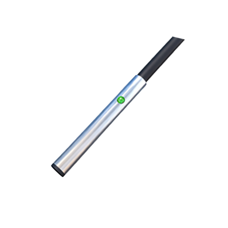
The nature of the target object itself dictates placement strategy. The sensor's effective sensing distance can be reduced depending on the target's material, size, shape, and approach direction. A standard inductive sensor's range is calibrated for mild steel. For stainless steel, copper, or aluminum, the effective sensing distance is less. Therefore, the sensor must be mounted closer. The target size should be at least equivalent to the sensor's face diameter for reliable detection. For small targets, like a screw head or a thin wire, the sensor needs to be positioned much closer, often requiring precise fixturing.
Another crucial aspect is the mounting method and mechanical protection. Sensors should be securely fastened to prevent vibration-induced movement, which alters the sensing gap. In high-vibration environments, using locking nuts or rigid brackets is essential. Furthermore, consider the physical hazards present. In machining applications, sensors should be placed outside the direct path of flying chips, coolants, or debris. If this is unavoidable, protective housings, baffles, or sensing face covers made of appropriate materials (like PTFE for non-stick properties) are necessary. For applications involving linear or rotary motion, ensure the sensor is not in a position where it could be struck or sheared by the moving parts.
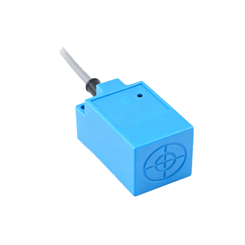
The electrical and wiring considerations also influence placement. While not directly about physical location, the routing of the sensor cable is part of the installation. Cables should be routed away from high-voltage lines and power conductors to prevent electrical noise coupling. Using shielded cables with proper grounding is recommended, especially for analog output sensors or in electrically noisy environments. The connection point (junction box, PLC cabinet) should be accessible for maintenance, but the sensor itself might be in a hard-to-reach location; therefore, choosing sensors with robust, pre-molded cables or quick-disconnect options can simplify future service.
Let's examine a few practical application examples. On a conveyor system detecting package presence, a photoelectric through-beam sensor is often ideal. The emitter and receiver are placed on opposite sides of the conveyor, ensuring the beam is broken by any object of sufficient size. The height should be set to detect the smallest acceptable package, but low enough to avoid false triggers from overhead structures. In a hydraulic press for part ejection verification, an inductive proximity sensor is typically embedded in the die or tooling. It must be positioned to detect the ejected part reliably after the press opens, while being fully protected from the immense forces and contaminants of the pressing operation. For liquid level control in a tank, a capacitive sensor is mounted on the outside of a non-metallic tank wall or inside a tank via a threaded fitting. The placement height corresponds directly to the desired level set point, and the sensor must be calibrated for the specific liquid's dielectric constant.
In conclusion, there is no single universal "best place" for a proximity sensor. The optimal location is a calculated compromise derived from understanding the sensor's technology, the