In industrial automation and motion control systems, achieving precise positioning is a fundamental requirement for efficiency, repeatability, and product quality. One common challenge is reliably stopping a moving object—such as a machine carriage, actuator, or robotic arm—directly at the center point of a proximity sensor's detection range. This technique, often called "centering" or "sensor-center stopping," is crucial for applications like part insertion, tool alignment, and assembly station indexing. While proximity sensors are excellent for non-contact detection, using them for precise positional stopping requires a clear understanding of their operating principles and careful system integration.
A proximity sensor, whether inductive, capacitive, or photoelectric, does not simply have an "on/off" point at a single distance. Instead, it possesses a defined sensing range or operating zone. Within this zone, the sensor's output state changes (e.g., from LOW to HIGH). The geometric center of this active detection zone is the ideal target point for precision stopping. Stopping at this center point maximizes tolerance for system variations like mechanical vibration, thermal expansion, or minor speed fluctuations, as it provides an equal margin of error in both directions within the sensing field.
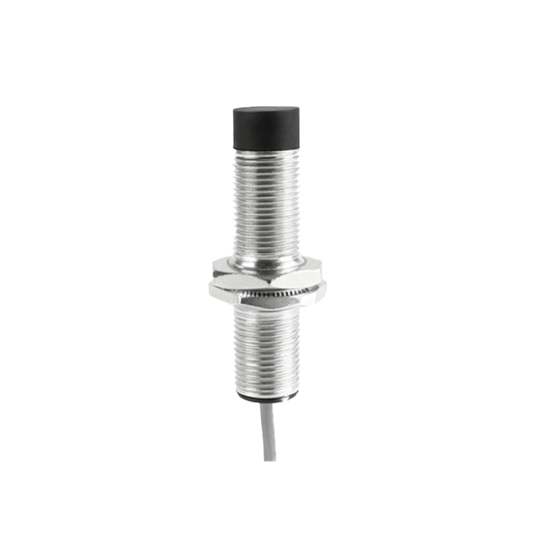
The primary method to achieve this involves a controlled deceleration profile. A simple "hard stop" upon the initial detection signal will invariably result in overshoot, leaving the target object somewhere past the sensor's activation point, not at its center. The correct approach is a two-stage or multi-stage motion sequence. First, the object moves at a high-speed approach velocity. Upon the initial trigger from the proximity sensor (entering its detection field), the motion controller immediately switches to a very low, creep-speed feed. The object continues to move slowly through the sensor's field. The controller then monitors the sensor's output state. The precise center point is typically defined as the midpoint between the switch-on point (where the output becomes active) and the switch-off point (where the output becomes inactive as the object moves past). Therefore, the logic is: trigger on sensor activation, reduce speed, and then trigger a complete stop command only after the sensor deactivates, positioning the object's reference point at the calculated center of the detection zone.
Implementing this requires attention to several critical factors. Sensor selection is paramount. The sensor must have a sharp, well-defined switching characteristic with minimal hysteresis (the difference between the operate and release points). A sensor with low hysteresis provides a smaller, more predictable window for finding the true center. The physical shape and size of the sensor's sensing face also matter; a smaller, more focused detection field allows for higher positional accuracy. Furthermore, the object being detected must be consistent in size, shape, and material, as these factors directly influence the sensor's effective sensing distance.
Integration with the motion controller is the next crucial step. The controller must support high-speed input interrupts for immediate response to the sensor signal. The deceleration ramp from high speed to creep speed must be fast and jerk-controlled to prevent mechanical shock. Programmable Logic Controllers (PLCs) or dedicated motion controllers execute logic like:IF Sensor=ON THEN Set Velocity to CreepSpeed; IF Sensor=OFF THEN Execute Immediate Stop and Set Position Register to Center_Zero_Point. Timing is critical; input filtering on the sensor signal should be minimized to reduce latency, which can cause positional error.
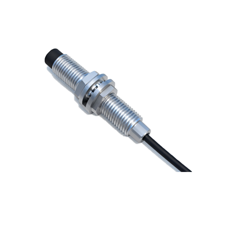
Calibration and tuning are indispensable. During system setup, the exact operate and release points must be mapped by moving the target object slowly through the sensor's range while recording positional data from an encoder or linear scale. This establishes the true geometric center. This calibrated center position is then stored in the controller as the target stop position. Regular maintenance checks are needed to ensure this calibration remains valid, as sensor performance can drift over time or due to environmental contaminants.
In practice, for ultra-high precision, a single proximity sensor may be supplemented with a secondary reference sensor or an encoder for closed-loop position verification. The proximity sensor provides the reliable "window" for the stopping sequence, while the encoder provides fine positional feedback to correct for any minor residual error, ensuring the final stopped position is exactly at the programmed center point.
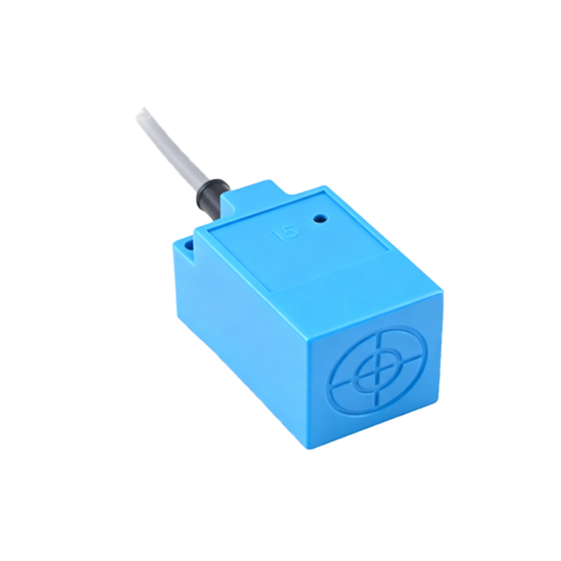
By mastering the technique of stopping at the sensor center, engineers can significantly enhance the precision of automated systems without resorting to more expensive and complex absolute positioning systems. It leverages the simplicity and robustness of proximity sensing while applying intelligent motion control logic to extract maximum positional accuracy, leading to improved process reliability and reduced cycle times in demanding industrial applications.