In the realm of industrial automation and control systems, the reliability and precision of sensing components are paramount. Among these, the 3-wire DC proximity switch sensor, particularly models designed for extended cable lengths up to 300 meters, represents a critical solution for long-range object detection in challenging environments. This article delves into the technical specifications, operational principles, wiring configurations, and key application considerations for these robust sensors.
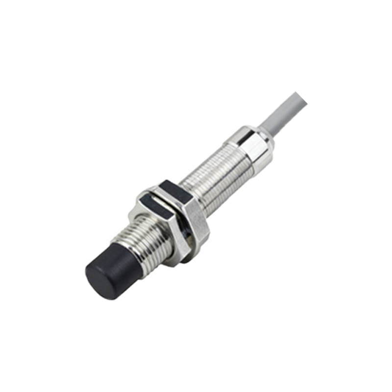
A proximity switch sensor is a non-contact electronic device that detects the presence or absence of a metallic target without physical contact. The 3-wire DC variant is one of the most common configurations, offering a simple interface with programmable logic controllers (PLCs) and other control units. The designation "3-wire" refers to the three essential connections: positive supply voltage (typically +24V DC), negative supply or ground (0V), and the switched output signal. The output can be either NPN (sinking) or PNP (sourcing), a crucial distinction that determines how the sensor interfaces with the load. The "300m" specification indicates the maximum permissible distance between the sensor head and the control system when using a recommended cable type, a feature that addresses the needs of large-scale installations like conveyor systems, mining operations, and extensive material handling plants.
The core technology behind these sensors is often based on the inductive principle. An internal oscillator generates a high-frequency electromagnetic field at the active face of the sensor. When a ferrous or non-ferrous metal target enters this field, eddy currents are induced in the target, causing a change in the oscillation amplitude. This change is detected by a threshold circuit, which subsequently triggers the solid-state output switch. For detecting non-metallic objects, capacitive or ultrasonic 3-wire sensors are employed, though the 300m cable run is most critical and common with robust inductive types.
The extended 300-meter capability is not merely a function of cable length but a result of careful engineering to mitigate signal degradation and voltage drop. Key factors enabling this performance include:
1. Output Circuit Design: Sensors designed for long distances often feature low output impedance and high current-switching capabilities to drive signals over long wires.
2. Cable Specifications: Using a shielded, twisted-pair cable with a sufficient conductor cross-section (e.g., 0.75 mm² or larger) is mandatory. The shield must be grounded at the control panel end to protect against electromagnetic interference (EMI) and noise, which can cause false triggering over long runs.
3. Supply Voltage Stability: A stable and well-regulated 24V DC power supply is essential. Voltage drop along the 300m cable must be calculated to ensure the sensor receives voltage within its operational range (usually 10-30V DC). In some cases, a higher supply voltage at the source or intermediate boosting may be necessary.
4. Leakage Current and Off-State Voltage: For 3-wire sensors, a small leakage current may flow even in the "off" state. Over 300m, this can lead to a residual voltage at the PLC input, potentially seen as an "on" signal. Selecting sensors with minimal leakage current and/or using a bleeder resistor at the PLC input module is a standard countermeasure.
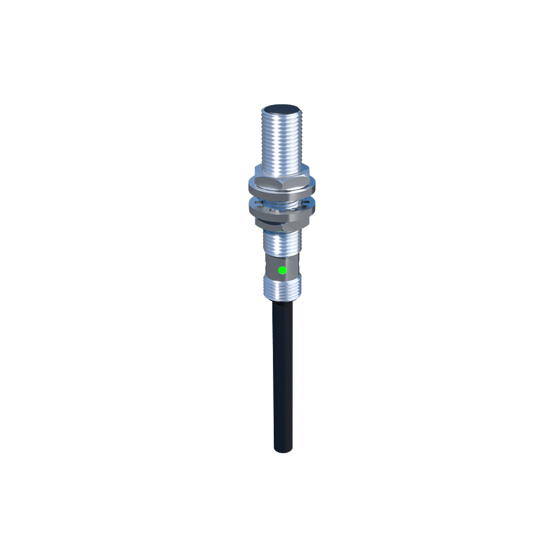
Wiring a 3-wire proximity sensor for a 300m application demands attention to detail. For a PNP (sourcing) sensor: the brown wire connects to +24V, the blue wire to 0V, and the black wire is the output, which will supply +24V to the load (e.g., PLC input) when activated. The load is then connected between the black wire and 0V. For an NPN (sinking) sensor: the brown wire connects to +24V, the blue to 0V, and the black wire is the output, which will connect the load to 0V when activated. The load is connected between +24V and the black wire. The cable shield should be connected to the functional earth (FE) terminal at the sensor (if available) and firmly to the ground at the control cabinet.
Application scenarios for a 3-wire 300m sensor are diverse. They are ideal for monitoring the position of crane trolleys over long tracks, detecting ore carts in mining tunnels, signaling package presence on airport baggage carousels, or providing remote limit switching on large gantry systems. Their sealed housings (often rated IP67 or IP69K) ensure resistance to dust, moisture, and mechanical impact.
When selecting such a sensor, engineers must specify:
Sensing Distance: The nominal range (e.g., 8mm, 15mm).
Output Type: PNP or NPN, normally open (NO) or normally closed