In the realm of industrial automation and electrical engineering, precise communication is paramount. Schematic diagrams serve as the universal language, and the symbols within them are the vocabulary. Among these, the graphic symbol for a capacitive proximity sensor is a critical element for designers, technicians, and engineers. This article delves into the standard representation, its components, and the practical implications of this symbol in circuit design and documentation.
The fundamental graphic symbol for a capacitive proximity sensor, as standardized by organizations like the International Electrotechnical Commission (IEC) and often adopted by the National Electrical Manufacturers Association (NEMA), is derived from the basic symbol for a capacitor. It typically consists of two parallel lines, representing the capacitor plates. This core element is then enclosed within a circle or a square, denoting the sensor housing or the active face of the device. The circle is the more common and internationally recognized enclosure for a generic proximity sensor symbol.
To convey its function as a switch, the symbol incorporates a switch contact notation. A standard non-contact capacitive sensor is normally open (NO). This is represented by a diagonal line intersecting the two capacitor plate lines, or more explicitly, by placing the capacitor-in-circle symbol adjacent to a standard normally open switch symbol (a line broken by a gap). The two components are often connected by a dashed line, indicating functional linkage rather than a physical electrical connection. The switch symbol is then integrated into the output circuit lines. For a normally closed (NC) output, the switch symbol would be shown as a closed contact.
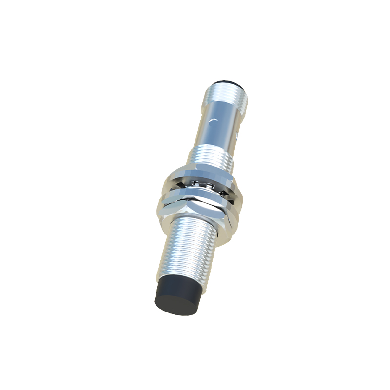
A crucial aspect of the symbol is the designation. The letters or numbers placed near the symbol provide essential information. Commonly, "C" or "CAP" may be used to distinguish it from an inductive proximity sensor (often "L" or "IND"). The IEC standard uses specific letter codes; for instance, a sensor might be labeled "B" for proximity switch. The sensor is also invariably marked with its supply connections, typically "+" and "–" for DC versions, or "L1" and "L2/L+" for AC/DC models. These are shown on the housing symbol. The output terminal (the switched line) is clearly indicated.
Understanding variations is key. Some schematics use a simplified symbol: just the capacitor-in-circle with the output line, omitting the explicit switch symbol, relying on the legend for clarification. Symbols also differ for specific types: Diffuse or background suppression capacitive sensors might have additional markings, like a small "B" or a different icon inside the circle, to show they are sensitive only to objects within a specific range, ignoring the background. Analog output capacitive sensors replace the switch symbol with a small amplifier or transducer symbol, with output lines marked for 0-10V or 4-20mA signals.
Why does this symbology matter? For Design Engineers, it allows for clear planning of machine logic, ensuring the sensor is correctly integrated with Programmable Logic Controllers (PLCs) and other components. The symbol immediately informs them of the sensor type, output state, and power requirements. For Maintenance Technicians, a correct schematic is the first line of defense in troubleshooting. Seeing the capacitive symbol, they understand the operating principle—detection based on dielectric constant changes—which guides diagnostic steps. For instance, they know that non-metallic materials (liquids, plastics, wood) or even level changes can trigger this sensor, unlike its inductive counterpart. For System Integrators, standardized symbols ensure consistency across documentation from different manufacturers, reducing errors during panel building and wiring.
In practice, when interpreting a schematic, one should always cross-reference the symbol with the parts list or bill of materials for the specific manufacturer's part number. The graphic symbol tells you what it does and how it connects; the datasheet tells you its precise specifications: sensing range, housing material, output current, and environmental ratings.
In conclusion, the graphic symbol for a capacitive proximity sensor is a elegant and information-dense shorthand. It encapsulates the device's physics (capacitance), its form (housed sensor), and its function (switching or analog output). Mastery of this symbol, and the family of sensor symbols, is not merely an academic exercise but a fundamental skill for anyone involved in the design, installation, or maintenance of modern automated electrical systems. It bridges the gap between a physical component on a machine and the abstract logic that controls it, ensuring clarity, safety, and efficiency from the drawing board to the factory floor.