Proximity switch sensors are fundamental components in modern industrial automation, playing a critical role in object detection, position sensing, and process control without physical contact. As an electrical engineer, ensuring these sensors are functioning correctly is paramount to maintaining system uptime and preventing costly production errors. This guide provides a systematic, industry-standard approach to checking and troubleshooting inductive, capacitive, and magnetic proximity sensors.
Initial Visual and Environmental Inspection
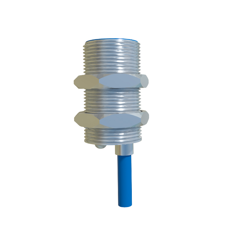
Before connecting any test equipment, conduct a thorough visual inspection. Look for signs of physical damage to the sensor housing, cable, or connector. Check for accumulated metal shavings, dust, or coolant on the sensing face, as these can severely affect performance, especially for inductive sensors. Verify the sensor's mounting. Ensure it is secure and properly aligned with the target. The sensing distance can be reduced if the sensor is loose or misaligned. Confirm the operating environment is within the sensor's specified ratings for temperature, humidity, and resistance to chemicals or washdowns.
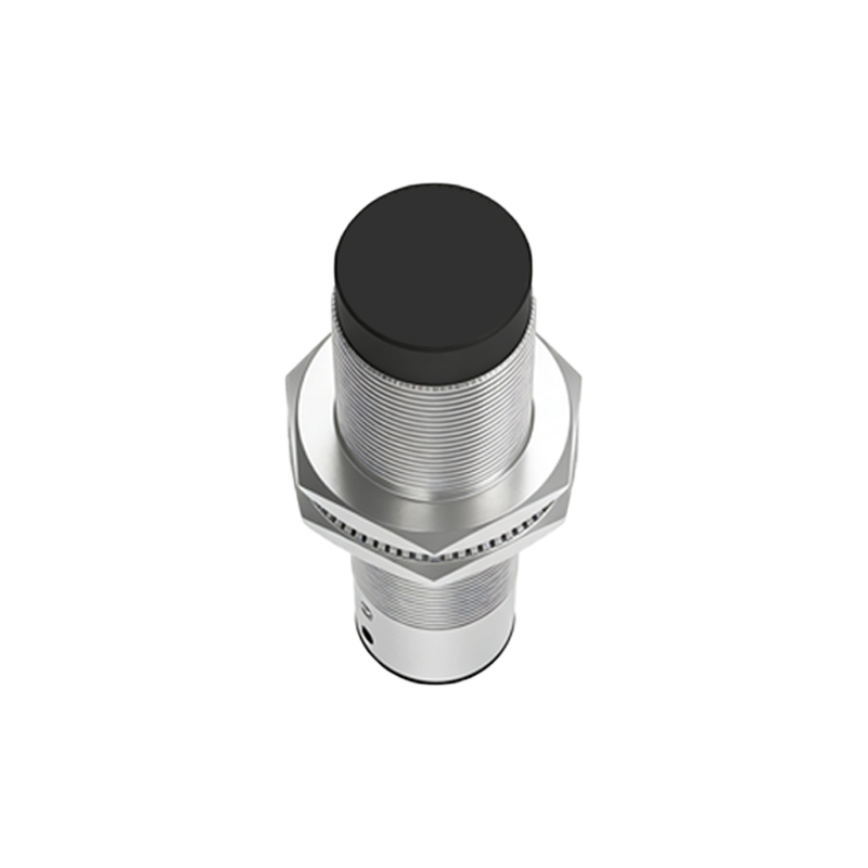
Verifying Electrical Specifications and Wiring
This is the most critical step. First, consult the sensor's datasheet to confirm its key specifications: operating voltage (e.g., 10-30V DC), output type (PNP/NPN, NO/NC), and current rating. Incorrect wiring is a leading cause of failure.
1. Power Supply: Use a digital multimeter (DMM) to measure the voltage between the supply positive (typically brown wire) and supply negative (typically blue wire) at the sensor's terminals or connector. Ensure it is stable and within the sensor's specified range. A low voltage can cause erratic operation.
2. Wiring Configuration: For a 3-wire DC sensor:
PNP (Sourcing): Brown to +V, Blue to 0V, Black is the switched output.
NPN (Sinking): Brown to +V, Blue to 0V, Black is the switched output (sinking to 0V).
Verify the load (e.g., PLC input, relay coil) is correctly connected between the output wire and the opposite supply rail (0V for PNP, +V for NPN).
3. Short Circuits: With power disconnected, use the DMM's resistance or continuity function to check for short circuits between wires, particularly between the output and either supply line.
Functional Testing with Target Simulation
After confirming correct power and wiring, test the sensor's switching function.
1. Output State Check (No Target): With power applied and no target in the sensing range, measure the voltage on the output wire. For a normally open (NO) sensor, the output should be "off" (≈0V for PNP, ≈Supply V for NPN). For a normally closed (NC) sensor, the opposite is true.
2. Activation Test: Introduce a valid target. For an inductive sensor, use the specified material (usually mild steel). Move the target axially towards the sensing face at the recommended switching distance. Observe the output change. Use the DMM to confirm the output voltage switches states. For a PNP NO sensor, the output should go from ~0V to near supply voltage.
3. Response and Consistency: Move the target in and out repeatedly. The sensor should respond consistently. An oscilloscope can be used to check for clean, bounce-free switching edges if high-speed operation is suspected. Listen for the internal relay click on AC-powered or relay-output sensors.
Advanced Diagnostics and Troubleshooting
If the sensor fails the basic tests, proceed with these steps:
LED Indicator: Most sensors have an LED that indicates power and output status. A solid LED with no target often indicates a wired NC configuration or a damaged output stage. A flashing LED may indicate a short-circuit protection mode.
Load Current Measurement: Use a DMM in series with the load or a clamp meter to measure the output current. Ensure it does not exceed the sensor's maximum rating. An overload can cause the sensor to shut down or fail.
Sensing Distance Check: The actual sensing distance (Sn) can degrade over time. Use a micrometer or gauge blocks to measure the exact distance at which the sensor reliably triggers. Compare this to the rated Sn from the datasheet. A significant reduction may indicate a failing oscillator circuit (in inductive sensors) or a damaged component.
Electrical Noise: In electrically noisy environments, sensor malfunction can be intermittent. Check for proper grounding of the metal sensor body and the machine. Use shielded cables, with the shield grounded at the control panel end only. Ferrite cores on the cable near the sensor can suppress high-frequency interference.
Preventive Maintenance and Best Practices
Regular