In industrial automation and control systems, proximity switch sensors are critical components for non-contact detection, providing vital digital or analog feedback. A common and frustrating issue encountered by maintenance engineers and technicians is when a proximity sensor fails to display a numerical readout on its connected indicator or HMI, despite seemingly functioning. This absence of numerical data can halt processes and obscure the root cause. This article delves into the systematic troubleshooting of this specific problem, focusing on an engineering perspective.
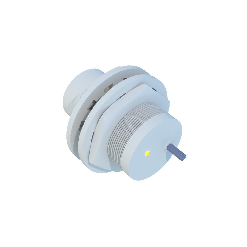
The first step is always to define the "no display" condition precisely. Is the display unit completely blank, showing dashes, or displaying an error code like "Err" or "OL"? A blank screen often points to a power supply issue, while specific error codes can guide the diagnosis more directly. Simultaneously, verify the sensor's basic operation. Many proximity sensors have a built-in LED that indicates target detection. Observe this LED. Does it illuminate when a metal (or other target material) is brought within the sensing range? If the sensor's own LED does not activate, the problem is likely with the sensor itself, its power, or its configuration, not primarily with the display.
Assuming the sensor's internal indicator LED functions correctly, the issue lies in the signal path between the sensor output and the display device. Here is a structured troubleshooting approach:
1. Power Supply Verification: This is the most fundamental check. Use a multimeter to measure the voltage at the sensor's power terminals. Ensure it matches the sensor's specifications (e.g., 10-30V DC). Check for stable voltage without excessive ripple or noise. Also, verify the power supply to the display unit or PLC input module. A brownout or overvoltage condition can cause displays to malfunction.
2. Wiring and Connections Inspection: Loose, corroded, or broken wires are frequent culprits. Physically inspect all connections from the sensor to the display, including terminal blocks, connectors, and junction boxes. Pay special attention to shield connections if using analog sensors (4-20mA, 0-10V) as improper grounding can induce noise that corrupts the signal. For a 3-wire DC sensor, confirm the correct wiring: brown wire to positive (+), blue wire to negative (-), and the black (or white) output wire to the load (display unit input). A swapped wire between the output and common can cause failure.
3. Sensor Output Type and Display Input Compatibility: A critical and often overlooked mismatch. Determine your sensor's output type:
Digital (Switching): NPN (sinking) or PNP (sourcing) transistor output.
Analog: Typically voltage (0-10V) or current (4-20mA).
Your display unit or PLC input must be configured to accept the exact same signal type. An NPN sensor cannot drive a PNP-input circuit directly without proper interfacing. An analog display set for 4-20mA will show nothing (or an error) if connected to a 0-10V sensor. Consult both datasheets to confirm compatibility.
4. Sensor Configuration and Scaling (Analog Sensors): For analog sensors measuring distance or pressure, the lack of a number often relates to incorrect scaling. The sensor outputs a raw analog signal (e.g., 12mA). The display device (meter, PLC, HMI) must be programmed with the correct scaling parameters to translate that mA value into a meaningful engineering unit (e.g., millimeters or bar). If the scaling is set to 0-10V but the signal is 4-20mA, the display will be incorrect or blank. Recalibrate the display's input channel according to the sensor's datasheet (e.g., 4mA = 0 mm, 20mA = 50 mm).
5. Load and Circuit Integrity: Check if the sensor's output is capable of driving the load. Some displays or PLC inputs have a low input impedance that can overload a simple transistor output. Measure the current in the output circuit. Also, use the multimeter in continuity mode to check for broken wires or high resistance in the signal path.
6. Environmental Factors and Sensor Health: Proximity sensors can be damaged by electrical transients, welding currents, excessive vibration, or chemical exposure. Even if the LED lights, the output transistor or analog circuit may be damaged, providing an incorrect voltage/current. Test the sensor output directly with a multimeter. For a digital sensor, measure the voltage between the output wire and common. It should switch between near-supply voltage and near-zero volts when a target is presented/removed. For an analog sensor, measure the current in series or voltage across the terminals to see if it changes smoothly with target movement.
7. Display Unit Diagnostics: Isolate the problem