In industrial automation and control systems, proximity sensors are indispensable components for non-contact detection of metallic or non-metallic objects. A particularly advanced application involves their operation through non-metallic walls or barriers, a concept often detailed in a "through-wall principle diagram." This article delves into the technical principles, typical circuit configurations, and key considerations for implementing such sensors, providing a clear explanation for electrical engineers and system designers.
The core technology enabling through-wall detection is primarily based on high-frequency oscillation, commonly found in capacitive or inductive proximity sensors. The principle diagram typically illustrates a sensor head containing an oscillator circuit that generates a high-frequency electromagnetic field. This field projects from the sensor's active face. When this field encounters a metallic object (for inductive types) or any material causing a change in dielectric constant (for capacitive types), it induces eddy currents or alters the capacitance in the sensing circuit. The control circuit, often an integrated circuit (IC) like a specialized comparator or a microcontroller unit (MCU), detects this change in oscillation amplitude or frequency.
The crucial aspect of the through-wall operation is that the sensor's electromagnetic field can penetrate non-conductive, non-metallic materials such as plastic, glass, or certain composite panels. The principle diagram will show the sensor mounted on one side of a barrier, with its sensing field penetrating the material to detect a target on the opposite side. The diagram annotates key parameters: the sensing distance (Sa), which is reduced compared to the nominal sensing distance in free air, and the thickness and material type of the barrier (often denoted as "wall thickness" and "material: e.g., PVC").
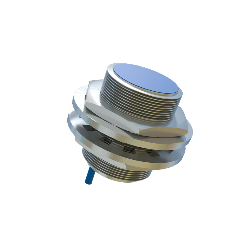
A standard through-wall principle diagram includes several key blocks:
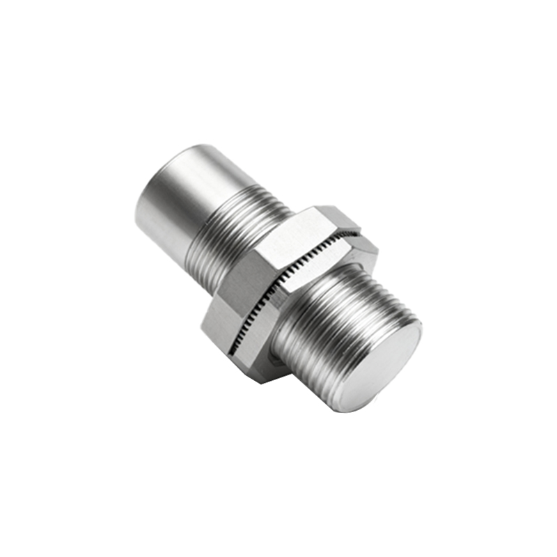
1. Sensor Oscillator & Coil/Capacitive Plate: This is the front-end where the high-frequency field is generated. In inductive sensors, a coil is the central element.
2. Demodulation & Amplification Circuit: This stage converts the minute changes in the oscillator's signal into a usable voltage level.
3. Threshold Comparator/Schmitt Trigger: This IC-based component compares the amplified signal to a preset reference voltage. When the signal exceeds the threshold (indicating target presence), the output state switches.
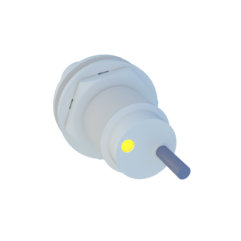
4. Output Stage: This is typically a solid-state switch (PNP/NPN transistor) or a relay driver. The diagram shows the connection to the load (e.g., a PLC input, relay coil, or indicator lamp) and the power supply lines (usually 10-30V DC).
5. Barrier Representation: A clear cross-section showing the sensor, the non-metallic wall, and the target object, with field lines depicting penetration.
Wiring is a critical part of the implementation. The diagram specifies a 3-wire or 2-wire configuration. A common 3-wire DC sensor wiring shows: Brown wire to DC+, Blue wire to DC-, and Black wire as the switched output. The load is connected between the Black wire and DC- (for NPN sinking output) or DC+ (for PNP sourcing output). Shielding and proper grounding are often indicated to prevent electromagnetic interference (EMI), which is more critical in through-wall applications due to potential signal attenuation.
Several factors influence performance, as highlighted in application notes accompanying the diagram:
Barrier Material and Thickness: Materials with low dielectric constants (like most plastics) are ideal. Thicker walls reduce the effective sensing range.
Target Material and Size: For inductive sensors, ferrous metals are detected at greater "through-wall" distances than non-ferrous metals. Larger target faces improve reliability.
Temperature Effects: Extreme temperatures can affect the oscillator's frequency and the barrier's properties, potentially requiring derating.
Mounting: Flush or non-flush mounting specifications must be adhered to, as they define the shape and reach of the electromagnetic field.
In conclusion, the proximity sensor through-wall principle diagram is an essential tool for engineers. It translates the abstract concept of field penetration into a concrete, actionable circuit and mechanical layout. By understanding each component and annotation on this diagram—from the oscillator circuit to the output driver and the critical barrier specifications—designers can reliably integrate these sensors into systems requiring hygienic separation, environmental protection (IP69K enclosures), or simply innovative mounting solutions. Always consult the specific manufacturer's datasheet for the exact diagram, specifications, and derating curves pertaining to their sensor model when designing a through-wall application.