Proper mounting is critical for the reliable operation of an M8 proximity sensor in any industrial automation or machinery setup. These compact, cylindrical inductive or capacitive sensors are ubiquitous for detecting the presence or absence of metallic objects without physical contact. Incorrect installation can lead to false triggers, reduced sensing range, physical damage, or complete failure. This guide details the correct procedures and best practices for mounting M8 proximity sensors to ensure optimal performance and longevity.
First, understand the sensor's specifications. Before installation, consult the sensor's datasheet. Key parameters include its sensing type (inductive for metals, capacitive for various materials), sensing distance (typically 1.5mm to 2mm for standard M8 inductive sensors), output type (PNP/NPN, NO/NC), and housing material (often nickel-plated brass or stainless steel). Also, note if it is shielded (flush-mountable) or unshielded (non-flush). Shielded sensors can be mounted flush in metal without affecting their sensing field, while unshielded sensors require a specific clearance from surrounding metal to operate correctly.
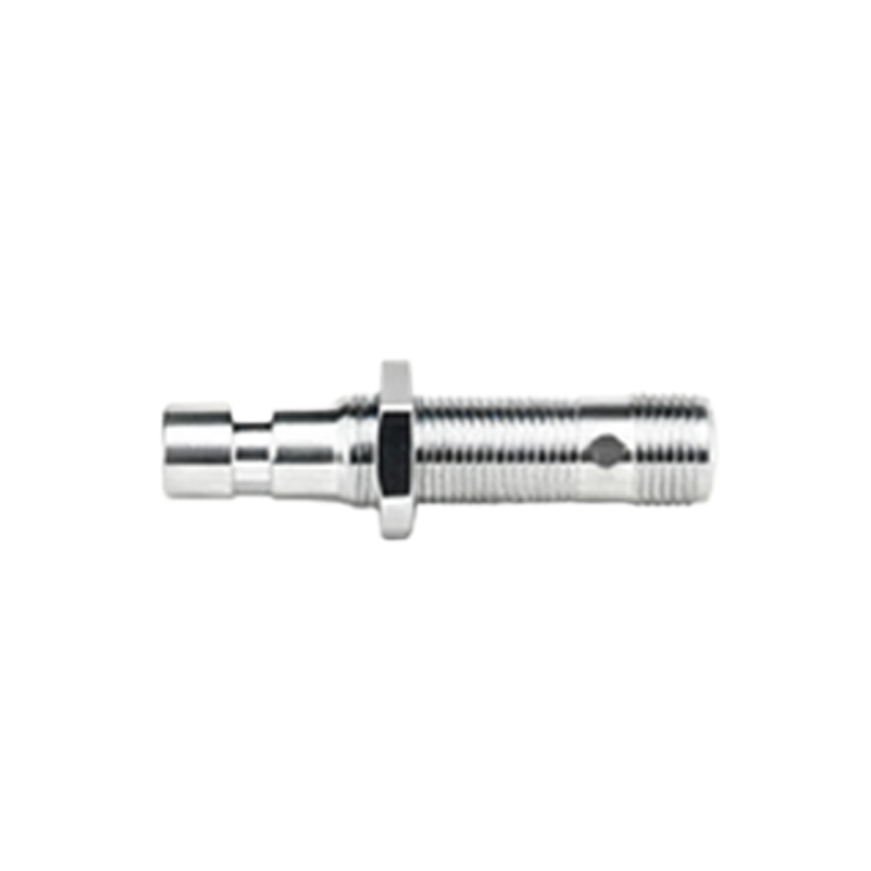
The core mounting method involves the sensor's M8 x 1.0 threaded barrel. Standard practice is to use a matching M8 nut, often two nuts supplied with the sensor, to secure it in a prepared mounting hole.
Step-by-Step Mounting Procedure:
1. Prepare the Mounting Location: Drill a clean, precise hole in the mounting bracket, panel, or machine structure. The recommended hole diameter is 8.0mm to 8.2mm for a standard M8 thread. The hole must be perpendicular to the expected path of the target object. Deburr the hole thoroughly to prevent damage to the sensor's threads or housing seal.
2. Consider Surrounding Metals: For unshielded sensors, maintain the required lateral and frontal clearance from any surrounding metal as specified in the datasheet (e.g., 1-2 times the sensor diameter). Failure to do this will drastically reduce the effective sensing distance. Shielded sensors can be installed flush with or into metal surfaces.
3. Insert and Position the Sensor: Screw the sensor into the prepared hole by hand until it is finger-tight. Do not use tools on the sensor housing itself, as this can cause torsion damage to internal components. Rotate the sensor body to align its sensing face correctly towards the target and to orient the cable outlet for optimal strain relief.
4. Secure with Locknuts: Once positioned, use the supplied hex nuts to lock the sensor in place. Typically, one nut is tightened against the mounting surface on each side (front and back) to prevent loosening from vibration—a common cause of failure in industrial environments. Use a wrench on the nuts, not the sensor body. Tighten securely but avoid over-torquing, which can strip threads or crack housings. A general torque specification is 5-10 Nm, but always refer to the manufacturer's guidelines.
5. Cable Management: For pre-wired models, route the cable through a cable gland or strain relief clamp immediately at the exit point. Ensure the cable is not twisted or subjected to sharp bends. Use cable ties or conduits to secure the cable along its path, preventing tension from being directly transferred to the sensor's electrical connections. For quick-disconnect (M8 connector) models, ensure the connector is firmly seated and, if applicable, screwed into the sensor's port.
6. Set and Test the Sensing Gap: The critical parameter is the operating gap—the distance between the sensor's sensing face and the target object in its detected position. This must be less than the rated sensing distance (Sn). For reliability, set the actual operating gap to 60-80% of the sensor's nominal Sn to account for mechanical tolerances, temperature drift, and vibration. Use a feeler gauge or shim for precise setting. Actuate the target object repeatedly and monitor the sensor's output LED and control signal to verify consistent switching.
Advanced Mounting Considerations:
Multiple Sensors: When mounting multiple M8 sensors side-by-side, maintain adequate spacing to prevent mutual interference. A minimum distance of 2-3 times the sensor diameter is a good rule of thumb, but datasheet specifications take precedence.
Harsh Environments: In washdown or outdoor applications, ensure the sensor has an appropriate IP rating (e.g., IP67, IP69K). Verify that the mounting hole seal (often an integral O-ring on the sensor's thread) is properly compressed against a smooth surface. Use of a sealing washer may be recommended.
Moving Sensor Applications: While typically mounted statically, if the sensor must be on a moving part, use flexible cable