In the realm of industrial automation and precision measurement, laser sensors stand as a cornerstone technology. Their ability to provide non-contact, high-accuracy, and high-speed detection makes them indispensable. For engineers and developers, moving beyond the black-box usage of these sensors to understand and potentially interact with their source code opens a new dimension of customization and optimization. This article delves into the typical architecture and key components of laser sensor firmware, written from the perspective of an industry practitioner.
At its core, the source code for a laser sensor—often referred to as firmware—is a sophisticated piece of embedded software. It is typically written in C or C++ for efficiency and direct hardware control. The primary function of this code is to manage the laser diode, interpret the reflected signal from a photodiode or a position-sensitive device (PSD), perform complex calculations, and output a reliable measurement or detection signal.
The firmware architecture usually follows a modular structure. A critical module is the Laser Driver Control. This section of the code is responsible for the precise modulation and pulsing of the laser diode. It interfaces directly with hardware timers and GPIO pins to ensure stable laser emission. Safety is paramount here; the code must include checks for current limits and temperature to prevent damage to the diode, often implementing a watchdog timer for fault recovery.
Following the emission, the Signal Acquisition and Conditioning module takes over. The analog signal from the receiving photodiode is digitized by an Analog-to-Digital Converter (ADC). The firmware here manages the ADC sampling rate, which is crucial for determining the sensor's response time and bandwidth. It also applies digital filtering algorithms, such as moving average filters or more advanced Infinite Impulse Response (IIR) filters, to remove electrical noise and enhance the signal-to-noise ratio (SNR). This clean signal is the raw material for all subsequent calculations.
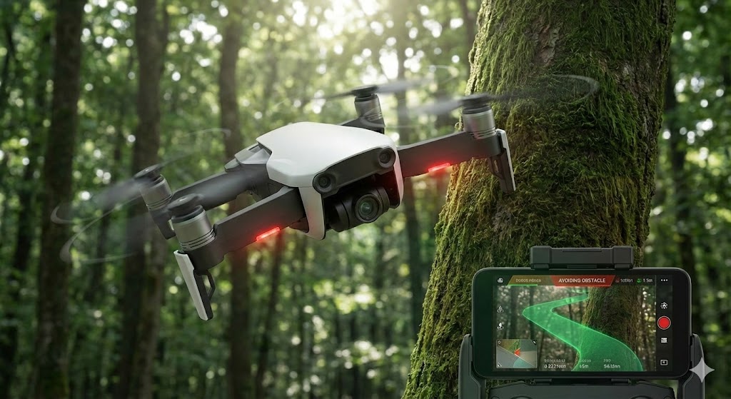
The heart of the intelligence lies in the Measurement Algorithm Module. For a time-of-flight (ToF) laser sensor, this involves calculating distance based on the phase shift or time delay between the emitted and received pulses. The code implements mathematical formulas, often involving fast Fourier transforms (FFT) for phase analysis or precise time interval measurements using hardware counters. For triangulation-based sensors, the algorithm calculates displacement based on the position of the laser spot on the PSD. This module is computationally intensive and is often optimized using fixed-point arithmetic to ensure speed on microcontrollers without floating-point units.
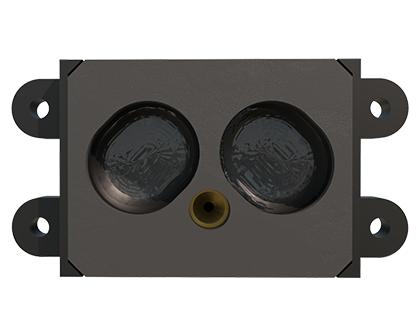
Once a measurement is computed, the Data Processing and Interface module handles the output. This includes applying user-configured parameters like tolerance windows, setting hysteresis to prevent output chatter, and triggering alarms if measurements fall outside defined limits. The code then formats the data for communication via standard industrial protocols such as IO-Link, PROFINET, EtherNet/IP, or simple analog/digital outputs. The protocol stack implementation, whether a vendor-specific library or an open standard, is a significant part of this module.
Configuration and Diagnostics form another essential layer. This allows users, via a software GUI or teach-in buttons, to set parameters. The firmware must parse these configuration commands, validate them, and store them in non-volatile memory (EEPROM or Flash). Comprehensive diagnostic routines are also coded to monitor hardware health, report status LEDs, and communicate error codes for maintenance.
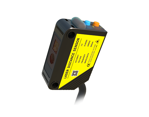
Developing or modifying such source code requires a rigorous approach. Engineers must have a deep understanding of the sensor's optical principle, the microcontroller's architecture, and real-time operating system (RTOS) concepts if used. Code efficiency is critical due to limited processing power and memory. Extensive testing under various environmental conditions—different surface materials, colors, ambient light, and temperatures—is mandatory to ensure robustness.
In conclusion, the source code of a laser sensor is a meticulously crafted blend of hardware abstraction, signal processing, and algorithmic computation. It transforms raw optical events into precise, industrial-grade data. While most applications utilize the sensor's pre-programmed functionalities, understanding this underlying code empowers engineers to tackle unique application challenges, perform deep diagnostics, and appreciate the engineering marvel embedded within these compact devices. The trend towards smarter, IO-Link enabled sensors is further pushing the boundary, allowing for more parameterization and data access, all driven by increasingly sophisticated firmware.