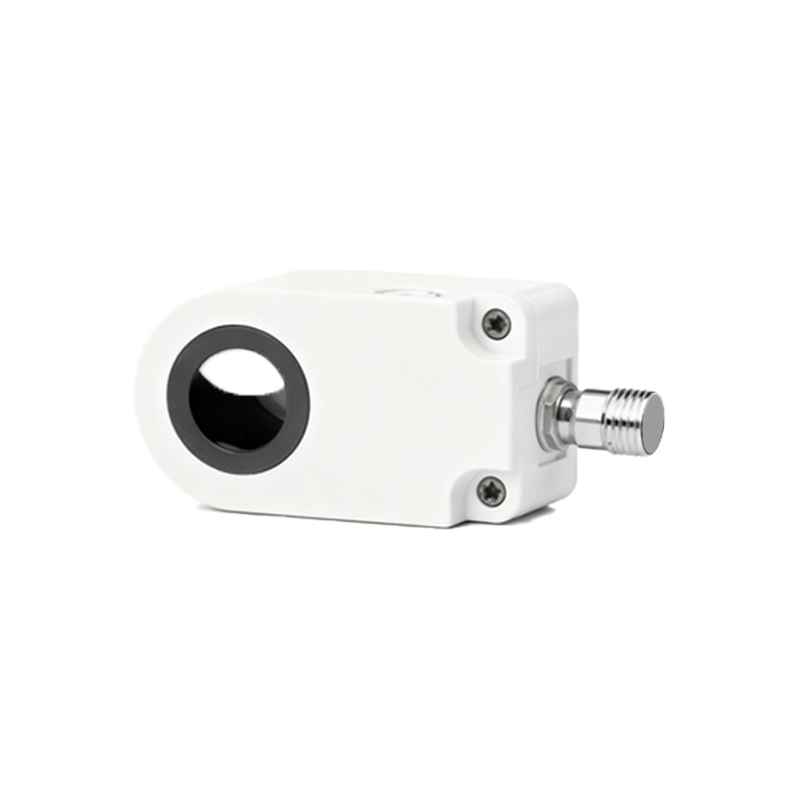
In the realm of industrial automation and control systems, capacitive proximity sensors are indispensable for detecting a wide range of materials—from metals and plastics to liquids and granular substances—without physical contact. While much attention is rightly given to the sensor's sensing face, frequency, and output type, the critical interface often overlooked is the sensor connector. The connector is the vital link ensuring signal integrity, power delivery, and environmental protection. A poor connection can lead to erratic behavior, false triggers, or complete system failure, undermining the reliability of an entire production line.
Capacitive sensor connectors are not universal; they are designed with specific electrical and mechanical characteristics. The most common types are quick-disconnect (QD) or M8/M12 style connectors, which have become industry standards due to their robustness and ease of use. M12 connectors, with their 4-pin or 3-pin configurations, are particularly prevalent. The pin assignment is paramount: typically, pin 1 is for the positive supply voltage (brown wire), pin 2 is for the output signal (black wire), pin 3 is not commonly used in DC sensors, and pin 4 is for the negative supply/ground (blue wire). Miswiring can damage the sensor or the connected programmable logic controller (PLC) input card. Always consult the sensor's datasheet, as color codes and pinouts can vary between manufacturers, especially for sensors with complementary (PNP vs. NPN) or analog outputs.
Selecting the correct connector involves several key considerations beyond just the physical thread size. First is the ingress protection (IP) rating. Sensors operating in washdown environments, like food and beverage processing, require connectors with high IP ratings (e.g., IP67 or IP69K) to withstand high-pressure, high-temperature spraying. The connector's material is another factor. Standard plastic (PBT) housings are sufficient for most applications, but chemically harsh environments may necessitate stainless steel or specialized chemically resistant polymer bodies. The cable gland integrated into the connector must also be compatible with the sensor cable's outer diameter to ensure a proper seal.
Installation is where theory meets practice, and precision is key. Begin by preparing the sensor cable: strip the outer jacket to the recommended length, then strip the individual conductors. For screw-clamp style connectors, insert the bare wire into the appropriate terminal chamber and tighten the screw firmly—but not excessively, as overtightening can shear the wire. For crimp-style connectors, use the manufacturer-specified crimping tool to attach the metal contact pins to the wires before inserting them into the connector housing. A proper crimp is gas-tight and provides superior mechanical and electrical connection. A common and critical mistake is allowing stray strands of wire to cause short circuits between terminals. After wiring, meticulously assemble the connector housing, ensuring all seals, O-rings, and the rear cable gland are correctly seated and tightened. A final tug test on each wire confirms they are securely held.
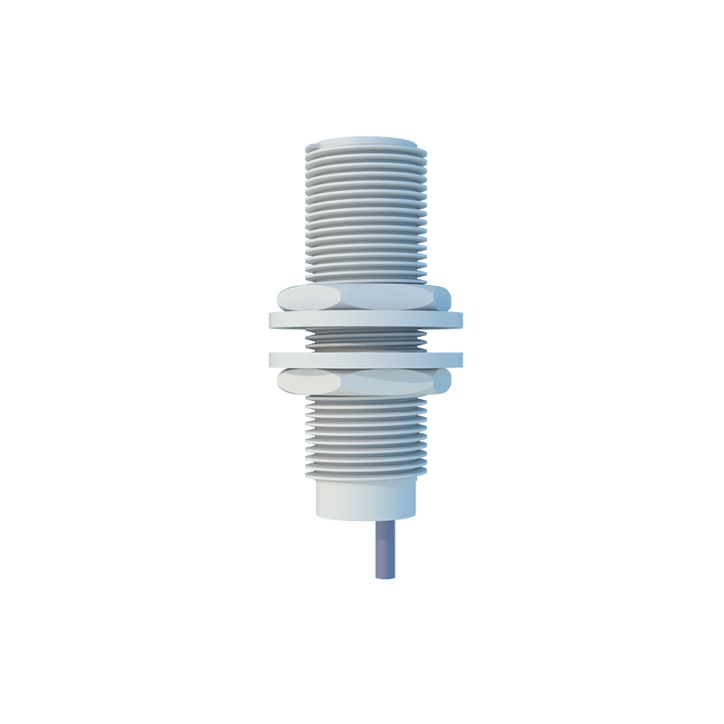
For long-term reliability, adherence to best practices is non-negotiable. Always de-energize the circuit before connecting or disconnecting sensors. Route sensor cables away from high-voltage power lines and motor drives to minimize electromagnetic interference (EMI), which can affect the sensitive capacitance measurement of the sensor. Use cable conduits or trays for physical protection and organized routing. Implement strain relief, either through the connector's built-in gland or external clamps, to prevent tension from being transferred to the electrical terminals. Periodically, as part of a preventive maintenance schedule, inspect connectors for signs of corrosion, cracked housings, or compromised seals. A simple continuity check with a multimeter can verify the integrity of the connection.
In conclusion, the humble connector is a linchpin in the performance of capacitive proximity sensing systems. By understanding the specifications, meticulously selecting the appropriate type for the application environment, and following rigorous installation procedures, engineers and technicians can ensure maximum uptime and signal reliability. This attention to detail transforms a collection of components into a robust, dependable system, capable of performing accurately in the demanding conditions of modern industrial automation.