Proximity sensors are fundamental components in modern industrial automation, robotics, and safety systems. Their ability to detect the presence or absence of an object without physical contact makes them invaluable. However, their performance is heavily dependent on correct installation, calibration, and configuration. This guide provides a comprehensive overview of the calibration process and directs you to reliable sources for downloading detailed manufacturer-specific tutorials and manuals.
Understanding Proximity Sensor Types
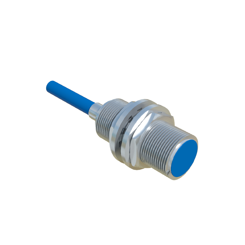
Before calibration, identify your sensor type. Inductive sensors detect metallic objects. Capacitive sensors can detect both metallic and non-metallic materials like liquids, plastics, or wood. Ultrasonic sensors use sound waves to measure distance to objects, while photoelectric sensors utilize light beams. Each type has a unique operating principle, which dictates its calibration methodology. Always refer to the sensor's datasheet for its specific sensing range, nominal voltage (e.g., 10-30V DC), output type (PNP/NPN, NO/NC), and housing material.
Pre-Calibration Checklist
1. Power Safety: Ensure the system is powered down and locked out (LOTO procedure) before wiring.
2. Installation: Mount the sensor securely. Pay attention to the recommended mounting distance from metal surfaces (for inductive sensors) to avoid side-effects. Ensure the target object moves within the specified sensing window.
3. Wiring: Connect wires correctly according to the datasheet—typically brown (V+), blue (V- or GND), and black (output signal). Incorrect wiring can cause permanent damage.
4. Environment: Check for environmental factors like temperature extremes, dust, moisture, or strong electromagnetic fields that could affect performance.
Step-by-Step Calibration Procedure
While procedures vary, a general calibration approach includes:
1. Power Up: Apply the correct voltage to the sensor. An LED indicator usually lights up to show power status.
2. Target Presentation: Introduce the standard target (the specific material, size, and shape the sensor is designed to detect) to the sensing face.
3. Distance Adjustment: For adjustable sensors, slowly move the target towards the sensing face. The effective sensing distance (Sn) is less than the nominal range. The indicator LED will activate when the target is within range.
4. Setting the Sensitivity: Many sensors have a potentiometer or teach-in function. Turn the potentiometer or activate the teach-in mode (often by pressing a button) with the target at the desired detection distance. This sets the trigger point. Avoid setting sensitivity at the absolute maximum limit; a 10-20% margin ensures reliability against environmental drift.
5. Hysteresis Check: Move the target in and out repeatedly. Note the "switch-on" and "switch-off" points. The difference is hysteresis, which prevents output chatter. Ensure it is stable.
6. Output Verification: Use a multimeter or PLC input to verify the output signal switches cleanly between high and low states (e.g., 24V and 0V) upon detection.
7. Final Testing: Run the target through the full range of operational speeds and angles to ensure consistent detection.
Troubleshooting Common Issues
No Output: Verify power and wiring. Check if the target is within range, of correct material, and large enough.
Intermittent Operation: Likely due to marginal sensitivity setting, unstable power supply, or environmental interference. Increase the margin or shield the sensor.
Short Sensing Range: Possible power voltage is low, sensor is misaligned, or the target is non-standard.
Sensor Always On: Possible wiring error (short circuit), sensor damage, or excessive buildup of material on the sensing face (for capacitive sensors).
Downloading Manufacturer Tutorials and Manuals
For precise, model-specific instructions, always download the official documentation. Here are reliable sources:
1. Manufacturer Websites: Leading brands like Sick AG, Pepperl+Fuchs, Omron Automation, Balluff, IFM Electronic, and Rockwell Automation (Allen-Bradley) maintain extensive online libraries. Navigate to "Support," "Downloads," or "Documentation" sections. Use the exact part number (e.g., IM12-04BPS-ZW1 or E2E-X5ME1) for best results.
2. Technical Portals: Many manufacturers offer centralized portals like Sick's Support Portal or IFM's ecolink.
3. File Formats: Tutorials are typically available as PDF manuals, datasheets, application notes, and sometimes video tutorials or CAD drawings.
4. Search Tips: Use keywords like