Magnetic proximity sensors are fundamental components in modern industrial automation, offering non-contact detection of ferromagnetic objects. Their operation relies on the interaction between a permanent magnet or an electromagnet within the sensor and a target object. The core principle involves detecting changes in a magnetic field. A typical sensor houses a reed switch or a solid-state Hall-effect element. When a ferromagnetic target, such as a steel gear tooth or actuator, approaches the sensor's active face, it disturbs the sensor's internal magnetic field. This disturbance causes the magnetic flux density to increase, triggering a state change in the sensing element.
For reed switch-based sensors, the increased magnetic flux causes the two ferromagnetic reeds inside a hermetically sealed glass capsule to attract and make contact, closing an electrical circuit. Hall-effect sensors, which are more robust and have faster switching frequencies, operate differently. A semiconductor Hall plate generates a small voltage (the Hall voltage) when exposed to a magnetic field. An integrated circuit within the sensor monitors this voltage. When the field strength exceeds a predefined threshold due to the target's proximity, the IC toggles the sensor's output signal.
The key performance parameters include sensing distance, hysteresis, and switching frequency. Sensing distance, often standardized (e.g., Sn), is the nominal range at which a standard target will reliably trigger the sensor. Hysteresis is a crucial feature that prevents output oscillation when a target is at the exact switching point; it creates a small difference between the switch-on and switch-off points, ensuring clean, single switching events. Switching frequency defines how quickly the sensor can respond to targets moving past it, critical for high-speed counting or position verification.
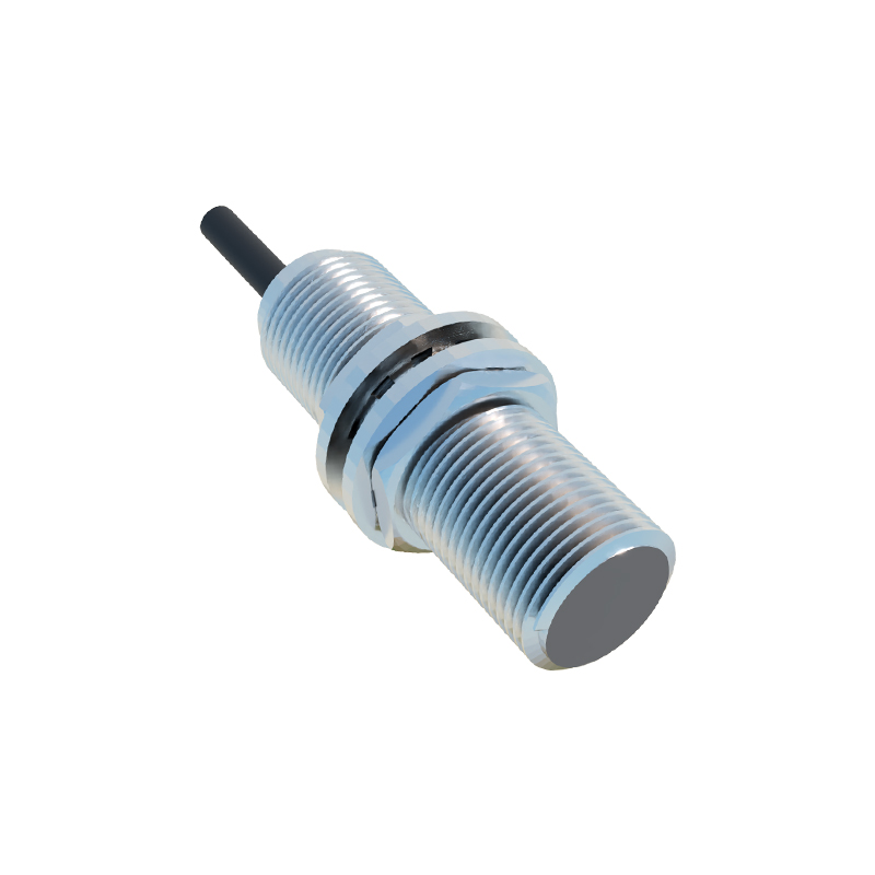
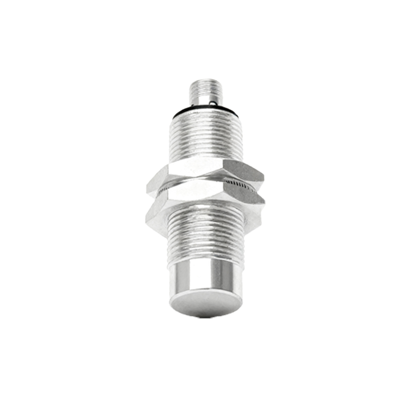
These sensors are prized for their durability. With no mechanical contact and typically solid-state construction (especially Hall-effect types), they are immune to wear from the sensing action itself. They are encapsulated in rugged housings, often made of stainless steel or nickel-plated brass, providing high resistance to vibration, shock, and harsh industrial environments including exposure to oils, coolants, and dust. Common housing forms include cylindrical barrels (e.g., M8, M12, M18 threads) and rectangular block styles.
Applications are vast across factory floors. They are extensively used for position detection of cylinders in pneumatic systems, where a small magnet integrated into the piston actuates the sensor at the end of stroke. They serve as limit switches on machine tools, detect the presence or absence of metal parts on conveyors, monitor rotational speed by counting gear teeth, and provide end-of-travel verification in automated guided vehicles. Their binary output (PNP/NPN, NO/NC) interfaces seamlessly with programmable logic controllers (PLCs) and other control systems.
When selecting a magnetic proximity sensor, engineers must consider the target material (must be ferromagnetic), the required sensing distance, environmental conditions (IP rating, temperature range), electrical requirements (voltage, output type), and housing style for proper mounting. Proper installation is also critical; sensors must be mounted securely without over-torquing, and adjacent magnetic sources or large ferrous structures should be avoided to prevent false triggering. Understanding these principles ensures reliable integration, contributing to robust and efficient automated system operation with minimal maintenance.