Three-wire proximity sensors are widely used in industrial automation for detecting the presence or absence of objects without physical contact. These sensors offer reliable performance in harsh environments and are essential components in machinery, conveyor systems, and robotic applications. Understanding their wiring is crucial for ensuring proper functionality, safety, and longevity. This guide provides a comprehensive overview of three-wire proximity sensor wiring, covering principles, configurations, and best practices.
A three-wire proximity sensor typically consists of three distinct wires: brown (positive supply), blue (negative or common), and black (output signal). The brown wire connects to the positive terminal of the DC power supply, usually ranging from 10 to 30 VDC, depending on the sensor model. The blue wire is linked to the negative or ground terminal of the power source, establishing the common reference point. The black wire serves as the output, which switches state (e.g., from high to low voltage) when an object is detected within the sensor's sensing range. This output can be either NPN (sinking) or PNP (sourcing), determining how the sensor interfaces with control systems like PLCs or relays.
For NPN-type sensors, the output wire connects to the load, which is then linked to the positive supply. When activated, the NPN sensor sinks current to ground, effectively closing the circuit to the load. This configuration is common in regions like Asia and Europe. In contrast, PNP-type sensors have the output wire connected directly to the load, with the load tied to the negative supply. Upon detection, the PNP sensor sources current from the positive supply, making it prevalent in North American applications. It is vital to match the sensor type with the control system's input requirements to avoid malfunctions or damage.
Proper wiring begins with selecting an appropriate power supply that matches the sensor's voltage and current specifications. Always refer to the manufacturer's datasheet for exact ratings. Use shielded cables in environments with electrical noise, such as those near motors or frequency drives, to prevent interference with the sensor's signal. Ground the shield at one end only, typically at the control panel, to avoid ground loops. Ensure all connections are secure and insulated, using crimped terminals or soldered joints to prevent loose wires that could lead to intermittent failures.
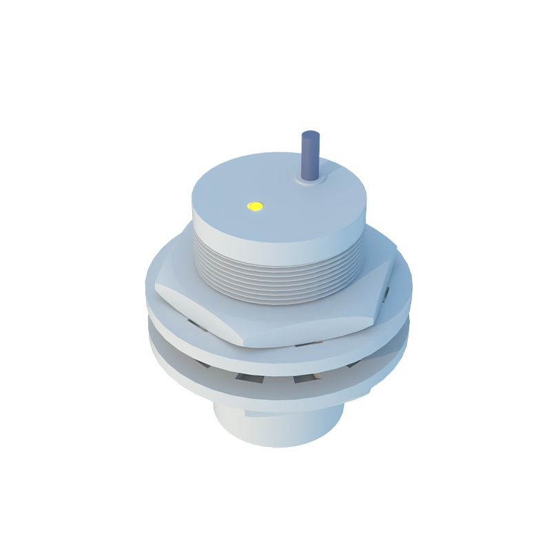
When integrating the sensor into a circuit, consider adding protective components like fuses or circuit breakers to safeguard against overcurrent conditions. For inductive loads, such as relays or solenoids, install flyback diodes or surge suppressors to mitigate voltage spikes that could harm the sensor's output transistor. Maintain proper cable routing, keeping sensor wires away from high-voltage lines to reduce electromagnetic interference. Label each wire clearly according to color codes and function to simplify troubleshooting and maintenance.

Testing the wiring involves applying power and verifying the sensor's response with a target object. Use a multimeter to check voltage levels at the output wire: it should read close to the supply voltage when inactive and drop to near zero (for NPN) or rise to supply voltage (for PNP) when activated. If the sensor fails to operate, inspect connections for continuity, confirm power supply integrity, and ensure the sensing range and object material are compatible. Regular maintenance, including cleaning the sensor face and checking for environmental contaminants like dust or moisture, enhances reliability.
In summary, three-wire proximity sensor wiring requires attention to detail regarding wire colors, sensor type (NPN or PNP), and environmental factors. By following standardized practices and adhering to manufacturer guidelines, engineers can achieve optimal performance, reduce downtime, and enhance system safety. As automation evolves, mastering these fundamentals remains key to efficient industrial operations.