Proximity sensors are essential components in industrial automation, providing non-contact detection of metallic or non-metallic objects. Correct wiring is crucial for ensuring reliable operation, safety, and longevity of these devices. This guide offers a detailed, step-by-step explanation of wiring methods for various types of proximity switches, accompanied by clear diagrams to assist engineers and technicians in proper installation.
Types of Proximity Sensors and Their Wiring Configurations
Proximity sensors are broadly categorized into three types based on their detection principles: inductive, capacitive, and ultrasonic. Each type has specific wiring requirements.
1. Inductive Proximity Sensors
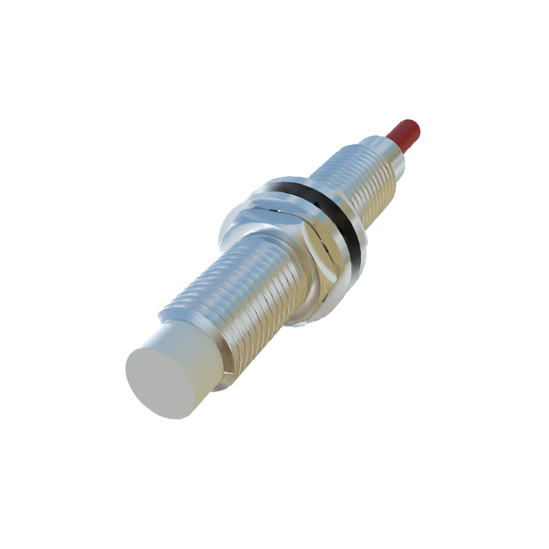
Inductive sensors detect metallic objects using electromagnetic fields. They typically have three wires: brown (power supply positive), blue (power supply negative or common), and black (output signal). For DC models, connect the brown wire to the positive terminal of the power source (usually 10-30V DC) and the blue wire to the negative terminal. The black wire connects to the load (e.g., PLC input, relay). In a 2-wire AC/DC configuration, one wire connects to the power source, and the other serves as both power and output. Ensure the load current does not exceed the sensor’s rated capacity to prevent damage.
2. Capacitive Proximity Sensors
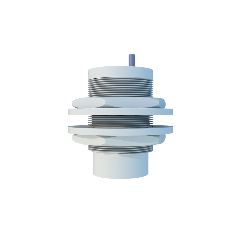
Capacitive sensors detect both metallic and non-metallic materials by measuring changes in capacitance. Wiring is similar to inductive sensors, with brown (positive), blue (negative), and black (output) wires. However, capacitive sensors often include a sensitivity adjustment potentiometer. When wiring, maintain a distance from high-voltage cables to avoid interference. Shielded cables are recommended for noisy environments.
3. Ultrasonic Proximity Sensors
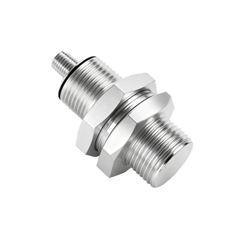
Ultrasonic sensors use sound waves for detection and are suitable for diverse materials. They generally have four wires: brown (V+), blue (V-), black (output 1), and white (output 2). Some models include analog outputs for distance measurement. Follow the manufacturer’s pinout diagram precisely, as wiring errors can lead to inaccurate readings or sensor failure.
Wiring Diagrams and Step-by-Step Instructions
A. 3-Wire DC Proximity Sensor Wiring
- Step 1: Identify the wires: brown (V+), blue (V-), black (OUT).
- Step 2: Connect the brown wire to the positive terminal of a 12-24V DC power supply.
- Step 3: Connect the blue wire to the negative terminal of the power supply.
- Step 4: Connect the black wire to the input module of a PLC or relay coil.
- Step 5: Connect the load’s other terminal to the power supply negative to complete the circuit.
- Diagram Note: The load (e.g., relay) is placed between the sensor output and ground. A flyback diode is recommended for inductive loads to protect the sensor from voltage spikes.
B. 2-Wire Proximity Sensor Wiring
- Step 1: Connect one wire to the power source positive.
- Step 2: Connect the other wire to the load, then link the load’s remaining terminal to the power source negative.
- Important: 2-wire sensors have no polarity; they can be wired in series with the load. Ensure the voltage drop across the sensor is within specifications to avoid malfunction.
C. NPN vs. PNP Output Configurations
- NPN (Sinking) Output: The output switches the negative side of the load. Common in Asian and European systems. Wire the load between the output and positive supply.
- PNP (Sourcing) Output: The output switches the positive side of the load. Preferred in North America. Wire the load between the output and negative supply.
- Diagrams for both configurations should clearly show the current flow path. Incorrect wiring may cause short circuits or no output signal.
Best Practices for Installation and Troubleshooting
- Always disconnect power before wiring to prevent electric shock or sensor damage.
- Use twisted-pair or shielded cables for long-distance wiring to reduce electromagnetic interference.
- Maintain proper clearance between sensors and metal surfaces to avoid false triggering.
- Regularly inspect connections for corrosion or looseness, especially in harsh environments.
- If the sensor fails, check power supply voltage, wiring continuity, and load compatibility. Refer to the datasheet for LED indicator status codes.
Conclusion
Proper wiring of proximity sensors is fundamental to industrial system performance. By following standardized diagrams and guidelines, engineers can ensure accurate detection, minimize downtime, and enhance operational safety. Always consult the manufacturer’s documentation for model-specific details, as wiring colors and pin assignments may vary. Implementing these methods will lead to efficient and reliable automation solutions.