In industrial automation and control systems, proximity sensors are ubiquitous components, prized for their non-contact detection capabilities. A common, yet critically damaging, installation error involves the accidental reversal of the sensor's signal output line with its 24VDC power supply line. This mistake, often stemming from hurried commissioning, mislabeled cables, or incorrect wiring diagrams, can lead to immediate and catastrophic failure of the sensor and potentially the connected control system input module. Understanding the electrical consequences, failure modes, and preventive measures is essential for every electrical engineer and technician.
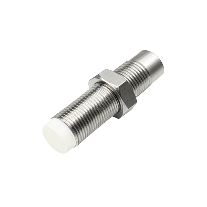
The standard three-wire DC proximity sensor configuration typically comprises a brown wire (24V+), a blue wire (0V/common), and a black wire (signal output). The internal circuitry is designed with specific semiconductor components, such as transistors or solid-state switches, to modulate the signal line. When 24V is incorrectly applied to the signal line (black wire), and the sensor's intended output signal is forced back into its own internal power rail (brown wire), a severe voltage mismatch occurs. The sensor's output stage, designed to sink or source a nominal current (e.g., 200mA) at a voltage close to the supply, is suddenly subjected to a full 24V potential in reverse. This almost invariably causes a breakdown of the output transistor or protection diodes. The result is a permanent short circuit or an open circuit on the output, rendering the sensor inoperative. In many cases, the internal voltage regulation or protection circuitry is also destroyed, sometimes with visible damage like popped capacitors or charred components.
The repercussions extend beyond the sensor itself. The misapplied 24V on the signal line travels directly to the receiving device, usually a Programmable Logic Controller (PLC) digital input card or a relay module. Most modern PLC inputs are designed with optical isolators and current-limiting resistors for a specific voltage range (e.g., 24VDC sinking/sourcing). Applying power into the input, rather than the input simply completing a circuit to common, can overwhelm these protective components. The opto-isolator's LED can be instantly destroyed by excessive reverse current or overvoltage, leading to a burned-out input channel. This necessitates costly repairs or replacement of the entire PLC input module, resulting in significant downtime.
Diagnosing this fault post-failure is usually straightforward. The sensor will not respond to targets, and a multimeter check will reveal an abnormal condition. Testing between the blue (common) and black (signal) wires may show a constant 24V (if the output is shorted) or 0V (if open), regardless of target presence. Resistance measurements across the sensor's power terminals might indicate a short. The corresponding PLC input LED will typically remain permanently on or off, unresponsive to commands.
Prevention is unequivocally the best and most cost-effective strategy. Adherence to a strict wiring protocol is paramount. This includes:
1. Color Code Verification: Always double-check wire colors against the sensor's datasheet. Do not assume standards; manufacturers can vary.
2. Terminal Labeling: Clearly label both ends of every cable during installation. Use permanent markers or printed tags indicating "24V," "COM," and "SIG."
3. Pre-Power Continuity Check: Before applying power, use a multimeter in continuity or resistance mode to verify that the brown wire from the sensor connects to the 24V+ source, the blue to 0V, and the black to the PLC input terminal.
4. Utilization of Protected I/O Modules: Consider using PLC input modules with built-in, robust protection against overvoltage and reverse polarity. Some modules feature redundant diode protection or self-resetting fuses.
5. External Protective Devices: Installing a small, fast-acting fuse (e.g., 100mA) or a polarity protection diode in series with the sensor's power line can provide an additional layer of safety, sacrificing a cheap fuse instead of an expensive sensor or PLC card.
6. Systematic Commissioning: Apply power in stages. First, power only the sensor and verify its indicator LED operates correctly with target actuation (using a non-metallic tool if necessary). Only after this verification should the signal line be connected to the control system.
In conclusion, reversing the signal and supply lines on a 24V proximity sensor is a severe electrical fault with damaging consequences for system integrity and operational uptime. The failure mechanism involves the destruction of sensitive semiconductor components due to reverse voltage application and overcurrent. By instituting rigorous wiring discipline, implementing verification checks, and considering additional protective hardware, engineers can effectively eliminate this common but preventable error, ensuring system reliability and longevity.