In industrial automation and machinery safety systems, proximity sensors play a critical role in detecting the presence or absence of objects without physical contact. Among various types, safety-rated proximity sensors are specifically designed for applications where human safety and equipment protection are paramount. The four-wire connection method is a common configuration for these sensors, offering enhanced functionality and reliability compared to two-wire or three-wire setups. This article delves into the principles, wiring procedures, and best practices for implementing four-wire safety proximity sensors.
A four-wire safety proximity sensor typically consists of two separate circuits: one for the sensor's output signal and another for a monitoring or diagnostic function. The four wires are usually color-coded for easy identification: brown for positive supply voltage (V+), blue for negative supply or ground (0V), black for the normally open (NO) or normally closed (NC) output signal, and white for the diagnostic or complementary output. This configuration allows the sensor to not only detect objects but also perform self-checks, such as monitoring for wire breaks, short circuits, or internal faults. In safety applications, this dual-channel design is essential for achieving higher Safety Integrity Levels (SIL) or Performance Levels (PL) as per standards like IEC 62061 or ISO 13849.
To wire a four-wire safety proximity sensor correctly, follow these steps. First, ensure the power supply matches the sensor's specifications, typically 10-30V DC for industrial models. Connect the brown wire to the positive terminal of the DC power source and the blue wire to the negative terminal. Next, link the black wire to the input of a safety relay or programmable logic controller (PLC) that processes the main detection signal. The white wire should be connected to a separate monitoring input on the safety device, enabling cross-checking of the sensor's state. It is crucial to use shielded cables in environments with electromagnetic interference (EMI) and to ground the shield properly to prevent false triggers. Additionally, always refer to the manufacturer's datasheet for specific wiring diagrams, as color codes or functions may vary between brands.
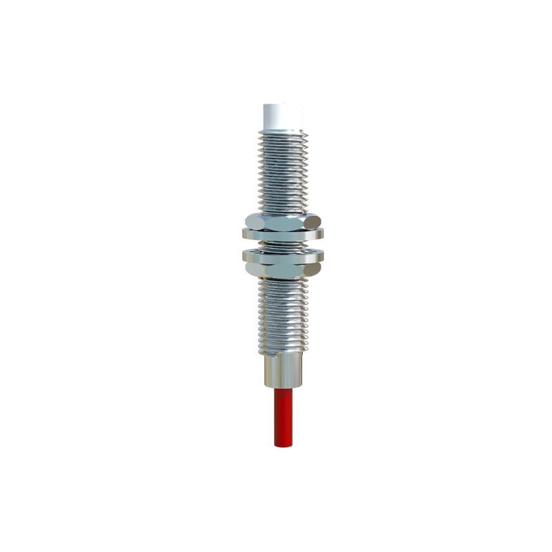
The advantages of the four-wire method are significant in safety-critical systems. The diagnostic capability reduces downtime by allowing early detection of faults, and the redundant output channels enhance reliability, preventing dangerous failures. For instance, in a machine guarding application, if the black wire's signal indicates an object is present (e.g., a person near a hazardous zone), the white wire can verify this state. Any discrepancy between the two signals triggers a safety shutdown, ensuring compliance with regulations like OSHA or EU Machinery Directive. Moreover, four-wire sensors often support flexible configurations, such as switching between NO and NC modes via wiring adjustments, making them adaptable to diverse industrial scenarios.
When installing these sensors, consider environmental factors like temperature, humidity, and exposure to chemicals, as they can affect performance. Regular maintenance, including checking connections for corrosion and testing diagnostic functions, is recommended to uphold safety standards. In summary, the four-wire connection method for safety proximity sensors provides a robust solution for modern automation, balancing detection accuracy with fail-safe operation. By understanding its wiring and applications, engineers can design safer and more efficient systems, ultimately protecting both personnel and machinery in industrial settings.