In the realm of industrial automation and control systems, proximity sensors are indispensable components for non-contact object detection. Among the various types, Inductive Proximity Sensors are particularly prevalent for detecting metallic objects. Two common classifications within this family are often designated as Type F and Type H. Understanding their distinct operational principles and characteristics is crucial for optimal sensor selection and system performance.
Fundamentally, both Type F and Type H sensors operate on the principle of electromagnetic induction. An oscillator generates a high-frequency electromagnetic field from the sensor's active face. When a metallic target enters this field, eddy currents are induced on the target's surface. This causes a change in the oscillation amplitude or frequency within the sensor, which is then processed by a trigger circuit to switch the output state. The core difference lies in the nature of this oscillator circuit and its resulting detection characteristics.
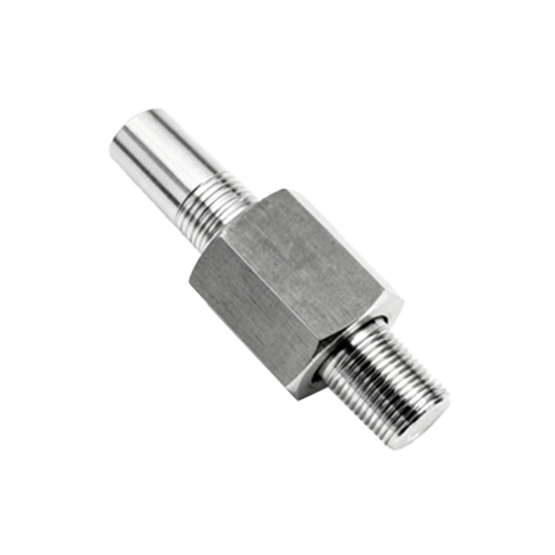
Type F sensors, typically known as "Shielded" or "Flush-mountable" sensors, feature a ferrite core that is concentrically wound and surrounded by a metal shield (often a copper ring) at the sensing face. This shielding design contains the electromagnetic field more tightly, directing it axially forward from the face. This allows the sensor to be installed flush with or embedded into a metal mounting bracket without the bracket influencing the sensing field and causing false triggers. The sensing range for a Type F sensor is generally standardized and relatively shorter. For instance, a standard 18mm diameter cylindrical Type F sensor might have a nominal sensing distance (Sn) of 5mm or 8mm. The field is concentrated, leading to a more precise and stable sensing point. The target approach characteristic is often more abrupt.
Conversely, Type H sensors are classified as "Unshielded" or "Non-flush-mountable." They lack the front metal shielding. Consequently, the electromagnetic field generated by the coil spreads laterally from the sides of the sensor as well as projecting forward. This results in a larger, more diffuse magnetic field. A key advantage is a longer sensing range compared to a similarly sized Type F sensor. An 18mm unshielded sensor might offer an Sn of 15mm. However, this unshielded design comes with a critical installation constraint: the sensor must be mounted with a clearance from any surrounding metal. If mounted flush in metal, the surrounding material will absorb the magnetic field, drastically reducing the effective sensing range or causing permanent activation. Manufacturer datasheets specify required free-space margins around the sensor body.
The performance implications of these designs are significant. Type F sensors excel in applications requiring precise, repeatable detection in cramped spaces or where sensors must be mounted directly into machine frames, actuators, or metal panels. Their shielded nature provides excellent resistance to electromagnetic interference from adjacent sensors or machinery. They are the default choice for embedded applications.
Type H sensors, with their extended range, are ideal for applications where the target must be detected from a greater distance or where mounting the sensor away from metal structures is feasible. They can sometimes detect smaller targets than a Type F sensor at the same nominal distance due to the wider field. However, system designers must carefully plan the mounting to maintain the necessary clearance.
Another subtle difference can be found in the sensing face behavior. The active face of a shielded (Type F) sensor is usually made of a non-metallic material like plastic or ceramic to allow the field to pass. The face of an unshielded (Type H) sensor is often a bare, molded plastic. The target material also influences performance differently. Both types are primarily for metals, but the reduction factor—the ratio by which the sensing distance decreases for metals like stainless steel or aluminum compared to mild steel—can vary slightly between designs. Engineers must always consult the specific sensor's datasheet for exact reduction factors.
In summary, the choice between a Type F (Shielded) and Type H (Unshielded) inductive proximity sensor hinges on the mechanical installation constraints and the required sensing distance. Use Type F for flush mounting in metal and applications demanding precise, localized detection. Opt for Type H when you need a longer range and can provide proper peripheral clearance. Misapplication can lead to system malfunctions, unreliable operation, or permanent sensor damage. Always adhere to manufacturer specifications for mounting, sensing distances, and target materials to ensure robust and reliable automation system performance.