Proximity sensors are critical components in pneumatic systems, providing non-contact detection of cylinder piston position. Their reliability directly impacts machine uptime and production efficiency. However, like any industrial component, they are subject to wear, environmental stress, and eventual failure. This guide details systematic maintenance and troubleshooting procedures to ensure optimal performance and longevity.
The most common types used with pneumatic cylinders are inductive and magnetic proximity sensors. Inductive sensors detect metallic piston flags, while magnetic sensors (often reed or Hall-effect types) detect a permanent magnet embedded in the piston. Understanding the type installed is the first step in effective maintenance.
Common Failure Modes and Symptoms
Failures rarely occur without warning. Typical symptoms include intermittent signal loss, failure to detect the target, constant "on" state, or erratic output. These issues often stem from:
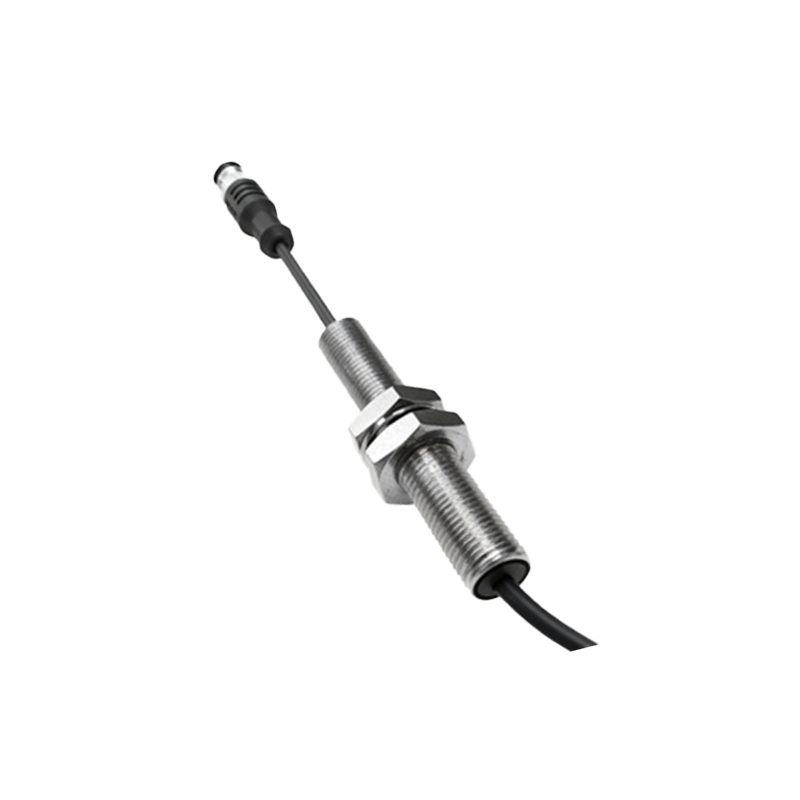
1. Mechanical Misalignment: The sensor body or its sensing face is knocked out of position, breaking the critical alignment with the piston's target (flag or magnet). Even a few millimeters can cause failure.
2. Sensor Face Contamination: Accumulation of metal chips, oil, grease, or other debris on the active sensing surface can dampen or block the sensing field.
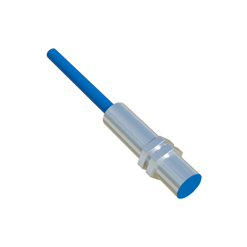
3. Wiring and Connection Issues: Vibration can loosen terminal screws, cause wire fatigue, or break internal connections. Damaged cable insulation can lead to short circuits.
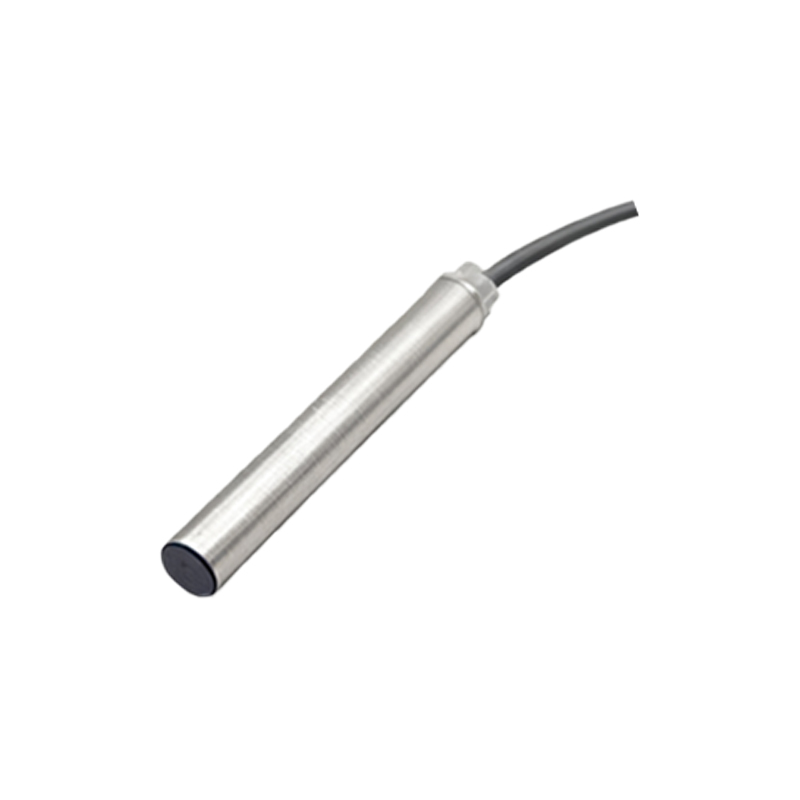
4. Electrical Overload or Noise: Voltage spikes, incorrect power supply, or excessive load current can damage internal circuitry. Electrical noise from nearby drives or welders can induce false signals.
5. Internal Component Failure: The oscillator in an inductive sensor or the semiconductor in a Hall-effect sensor can degrade over time.
Step-by-Step Maintenance & Troubleshooting Procedure
Follow this logical sequence to diagnose and resolve issues. Always adhere to lockout/tagout (LOTO) procedures before beginning work.
1. Visual and Mechanical Inspection:
Power down the system and isolate air pressure.
Inspect the sensor housing for cracks, dents, or signs of impact.
Check the mounting brackets and hardware for tightness.
Verify the alignment. Use a feeler gauge to ensure the gap between the sensor face and the piston's travel path is within the manufacturer's specified range (typically 0.5-2mm). The target must pass directly over the center of the sensing face.
Thoroughly clean the sensor face with a soft, lint-free cloth and isopropyl alcohol. Remove all contaminants.
2. Electrical Inspection:
Verify the power supply voltage at the sensor terminals matches the sensor's rating (e.g., 10-30V DC). Use a multimeter.
Inspect the cable and conduit for cuts, abrasion, or pinch points.
Check all connections at the sensor, junction box, and PLC input card for tightness and corrosion.
Measure the output. For a 3-wire DC sensor, with power applied and a target present, the voltage between the output wire (usually black) and negative should be near 0V (sinking) or near supply voltage (sourcing). Without a target, it should be the opposite. An incorrect reading indicates a faulty sensor or load.
3. Functional Testing:
Temporarily bypass the machine's control logic if safe to do so.
Manually cycle the cylinder and observe the sensor's indicator LED (if equipped). It should illuminate steadily when the target is present.
Use a multimeter or oscilloscope to monitor the output signal for a clean, swift transition without chatter or noise.
For a quick check, substitute a known-good sensor of the exact same type. If the problem resolves, the original sensor is faulty.
Preventive Maintenance Best Practices
Schedule Regular Inspections: Incorporate sensor checks into weekly or monthly PM schedules. Include alignment verification, face cleaning, and connection tightening.
Improve Installation: Use sturdy, adjustable mounting brackets. Ensure cables are properly strain-relieved and routed away from heat and moving parts.
Protect the Sensor: Install protective shrouds or guards in high-impact risk areas. In dirty environments, select sensors with higher IP ratings (e.g., IP67).
Manage Electrical Environment: Use shielded cables, grounded properly at one end. Install surge suppressors on solenoid coils and consider noise filters on sensitive sensor lines.
Keep Spares: Maintain an inventory of critical sensor models to minimize downtime during replacement.
Replacing a faulty