Proximity switches are fundamental components in modern industrial automation, providing non-contact detection of objects within their sensing range. These devices are widely used in manufacturing, packaging, robotics, and material handling systems due to their reliability, durability, and precision. An image of a proximity switch often reveals key physical and functional characteristics that are essential for engineers and technicians to understand during selection, installation, and troubleshooting.
A typical proximity switch image showcases a compact, cylindrical or rectangular housing, usually constructed from materials like nickel-plated brass, stainless steel, or rugged plastics such as PBT. This housing is designed to withstand harsh industrial environments, including exposure to dust, moisture, oils, and mechanical vibrations. The image may highlight the device's sensing face, which is the active area where the electromagnetic or capacitive field is emitted. For inductive proximity switches—the most common type used for detecting metallic objects—the sensing face is often a flat or slightly recessed surface. In contrast, capacitive proximity switches, which can detect both metallic and non-metallic materials, might have a different face design to optimize sensitivity.
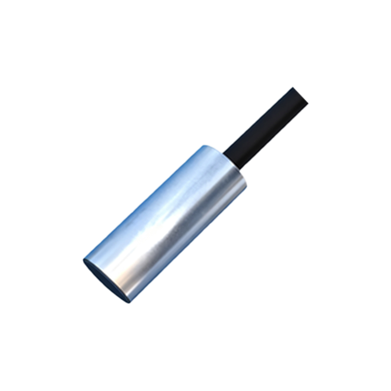
Examining the wiring connections in a proximity switch image is crucial. Most industrial proximity switches feature a cable exit or a connector system, such as a quick-disconnect M12 or M8 connector, which simplifies installation and maintenance. The image may show three or four wires, typically color-coded: brown for positive supply voltage (V+), blue for negative or common (V-), black for the output signal (normally open or normally closed), and sometimes white for a complementary output or diagnostic function. Understanding these connections from a visual reference helps ensure correct integration into control systems like PLCs (Programmable Logic Controllers).
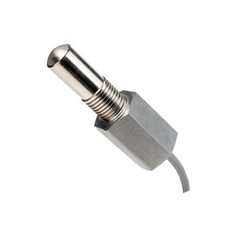
The internal components, though not always visible in external images, are implied by the switch's specifications. Inductive proximity switches contain an oscillator coil, a demodulator, and a solid-state output circuit. When a metallic object enters the sensing range, it dampens the oscillator's electromagnetic field, triggering the output to change state. This operation is often depicted in diagrams accompanying product images, illustrating the switch's sensing range, which can vary from a few millimeters to several centimeters depending on the model and target material.
In practical applications, images of proximity switches installed on machinery provide context. For instance, a photo might show a switch mounted on a conveyor bracket, positioned to detect passing metal parts, or integrated into a robotic gripper to confirm object presence. These application images emphasize the importance of proper mounting—ensuring the sensing face is aligned correctly and free from obstructions—and highlight environmental considerations, such as maintaining adequate clearance from other metal surfaces to prevent false triggering.
Technical specifications derived from images and datasheets include the sensing distance, rated voltage (commonly 10-30V DC or 90-250V AC), output type (PNP or NPN for DC models), switching frequency, and protection ratings like IP67 or IP69K for resistance to water and dust. Visual cues, such as LED indicators on the switch body, are also valuable; a glowing LED often signals power presence and output activation, aiding in real-time diagnostics.
When selecting a proximity switch based on images and data, engineers must consider the target material, required sensing range, environmental conditions, and electrical compatibility. For example, a stainless-steel housing might be chosen for washdown areas in food processing, while a shielded (flush-mountable) version could be selected for tight spaces where side-sensitive detection is necessary.
In summary, a proximity switch image serves as a practical tool for identification and application planning. By analyzing its physical design, connection details, and contextual installation, professionals can make informed decisions that enhance system reliability and efficiency. As automation evolves, with trends toward miniaturization and smart sensors offering IO-Link communication, these images will continue to be a vital reference for implementing advanced industrial solutions.