As an experienced electrical engineer in industrial automation, I often encounter questions about properly setting up and debugging proximity sensors. These non-contact devices are crucial for detecting the presence or absence of objects in countless applications, from assembly lines to robotic systems. However, incorrect installation or calibration can lead to false triggers, missed detections, and costly downtime. This guide provides a clear, step-by-step approach to debugging proximity sensors, accompanied by explanatory images to visualize each stage.
First, understand the sensor type. Inductive proximity sensors detect metallic objects, while capacitive sensors can sense both metallic and non-metallic materials. Photoelectric sensors use light beams, and ultrasonic sensors rely on sound waves. Each type has unique debugging considerations. For instance, inductive sensors may require adjustment based on the target metal's properties, while photoelectric sensors need alignment checks.
Step 1: Verify Power Supply and Wiring.
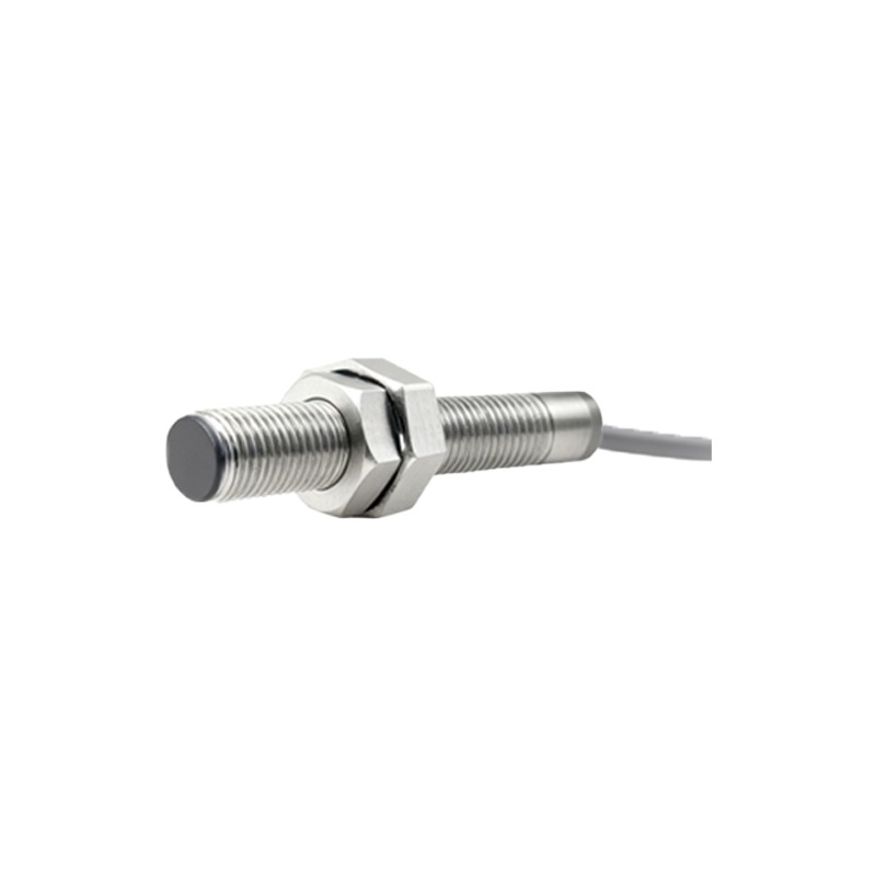
Begin by checking the electrical connections. Ensure the sensor is connected to the correct voltage supply (e.g., 12-24V DC for many models) as per the datasheet. Incorrect polarity can damage the sensor. Use a multimeter to measure voltage at the sensor terminals. A stable reading within the specified range is essential. Refer to Image 1, which shows a typical wiring diagram for a three-wire DC sensor, highlighting power, ground, and output connections. Loose wires or poor contacts often cause intermittent failures.
Step 2: Assess Installation and Mounting.
Proper mounting is critical for reliable operation. Ensure the sensor is securely fixed, with no vibrations that could affect performance. For inductive and capacitive sensors, maintain the recommended sensing distance from the target object. Avoid mounting near metal surfaces or other sensors that might cause interference. Image 2 illustrates correct vs. incorrect mounting scenarios, emphasizing alignment and clearance. If the sensor is too close to other equipment, electromagnetic or acoustic noise may lead to false signals.
Step 3: Adjust Sensitivity and Sensing Range.
Many proximity sensors feature adjustable sensitivity potentiometers or teach-in functions. For inductive sensors, adjust the sensitivity to account for different metals—steel typically has a longer sensing range than aluminum. Use a target object of the correct size and material to test. Gradually increase sensitivity until the sensor reliably detects the object, then reduce it slightly to avoid oversensitivity. Image 3 demonstrates adjusting a potentiometer on an inductive sensor, with a graph showing how sensitivity affects the detection range. For photoelectric sensors, align the emitter and receiver precisely, and adjust the beam intensity if available.
Step 4: Test with Actual Targets.
Simulate real operating conditions by moving the target object through the sensing area at the expected speed. Observe the sensor's output indicator LED, which should illuminate when an object is detected. Use an oscilloscope or PLC to monitor the output signal for consistency. If the sensor fails to trigger, check for obstacles, dirt, or environmental factors like humidity or temperature extremes. Image 4 shows a test setup with a metallic plate approaching an inductive sensor, capturing the moment of detection with a clear signal output.
Step 5: Troubleshoot Common Issues.
If problems persist, systematic troubleshooting is key. For false triggers, consider electrical noise from nearby motors or frequency drives. Shield cables and ensure proper grounding. For reduced sensing range, clean the sensor face from oil, dust, or debris. Capacitive sensors might be affected by changes in material density or moisture. Refer to the manufacturer's manual for error codes or diagnostic modes. Image 5 summarizes a troubleshooting flowchart, covering steps like checking load current, environmental conditions, and sensor health.
Step 6: Validate in the System Context.
Finally, integrate the sensor into the larger control system, such as a PLC or microcontroller. Verify that the output signals are correctly interpreted and that timing aligns with process requirements. Document settings for future maintenance. Regular calibration checks, especially in harsh environments, can prevent unexpected failures.
In summary, debugging proximity sensors involves a mix of electrical checks, mechanical adjustments, and environmental considerations. By following these steps and using the images as references, engineers can ensure optimal performance and longevity. Always consult the specific sensor's documentation, as features may vary. With practice, debugging becomes a quick, routine task that enhances system reliability and efficiency.