In industrial automation and control systems, 3-wire DC proximity sensors are ubiquitous components for non-contact detection of metallic objects. Their reliability and ease of integration hinge on correct wiring. This guide details the fundamental principles and practical steps for wiring these sensors, ensuring optimal performance and system safety.
A standard 3-wire DC proximity sensor has three distinct leads, typically color-coded as Brown, Blue, and Black (though colors can vary by manufacturer; always consult the datasheet). These correspond to three essential electrical connections:
1. Brown Wire: This is the positive supply voltage line (+V). It must be connected to the positive terminal of the DC power source. The operating voltage range (e.g., 10-30 VDC) is specified on the sensor's label.
2. Blue Wire: This is the negative supply voltage line, or common (0V/GND). It must be connected to the negative terminal of the DC power source.
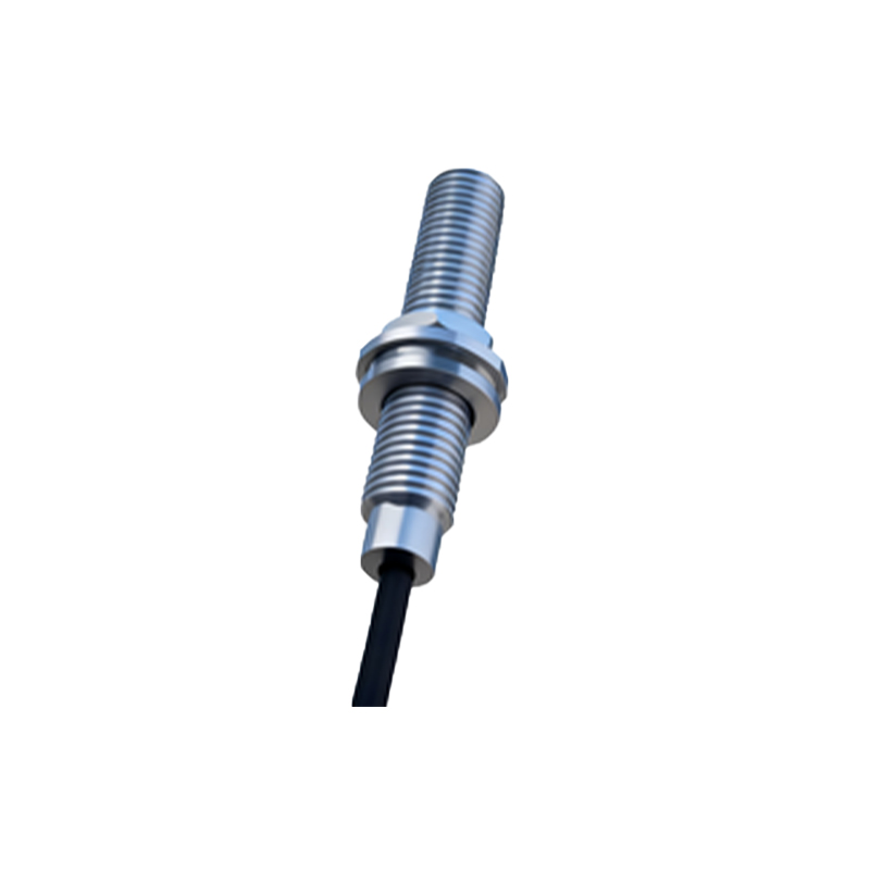
3. Black Wire: This is the signal output line. The function of this wire defines the sensor's output type. In a sourcing (PNP) sensor, the Black wire outputs a positive voltage (close to the supply voltage) when a target is detected. In a sinking (NPN) sensor, the Black wire switches to a low voltage (near 0V) or connects to ground when activated.
The critical first step is identifying whether your sensor is PNP (sourcing) or NPN (sinking). This determines how it interfaces with the controller (PLC, relay, input module). A PNP sensor is typically used with a PLC input card configured to accept a sourcing signal. Conversely, an NPN sensor pairs with a sinking-input PLC card. Mismatching these can lead to non-operation or potential damage.
Basic Wiring Procedure:
1. Power Off: Always disconnect power before beginning any wiring work.
2. Identify Wires: Confirm the wire colors and their functions using the sensor's documentation. Assume Brown (+V), Blue (0V), and Black (Signal) for this guide.
3. Connect Power:
Connect the Brown wire to the positive (+) terminal of your DC power supply (e.g., 24VDC).
Connect the Blue wire to the negative (-) terminal of the same DC power supply.
4. Connect the Output:
For a PNP Sensor: Connect the Black wire to the load (e.g., one side of a PLC digital input). The other side of the PLC input must be connected to the power supply's 0V (Blue wire terminal).
For an NPN Sensor: Connect the Black wire to the load (e.g., one side of a PLC digital input). The other side of the PLC input must be connected to the positive supply voltage (+V/Brown wire terminal).
5. Verify and Test: After securing all connections, restore power. Use a metallic target to actuate the sensor. Verify the output response with a multimeter or by observing the PLC input indicator.
Crucial Considerations for Reliable Operation:
Load Compatibility: Ensure the connected load (PLC input, relay coil) is compatible with the sensor's output current and voltage ratings. Do not exceed the maximum switching current.
Short-Circuit Protection: Many modern sensors include built-in protection against output short-circuits. However, it is good practice to implement external fusing or current-limiting circuits in the supply line for system-wide protection.
Shielding and Noise: In electrically noisy environments, use shielded cables. Connect the cable shield to earth ground at one end only (usually the control panel end) to prevent ground loops. Keep sensor cables away from high-voltage power lines and motor drives.
Wiring Integrity: Use proper crimping tools and terminals. Ensure wires are securely fastened to prevent loose connections, which are a common source of intermittent faults.
Sensor Mounting: Follow manufacturer guidelines for flush or non-flush mounting distances to the sensing face, as this affects the rated sensing range.
A common wiring mistake is interchanging the Brown and Blue wires, which will likely destroy the sensor. Another frequent error is misunderstanding the NPN vs. PNP circuit completion path. Remember: a PNP sensor sources current to the load, while an NPN sensor sinks current from the load. Always double-check the sensor model and the PLC input specification before energizing the circuit.
By meticulously following these wiring principles—correctly identifying the sensor type, connecting power polarity accurately, and interfacing the output signal appropriately—you ensure a robust and fault-free installation. Proper wiring is not merely a connection