Proximity sensors are essential components in modern automation and control systems, detecting the presence or absence of objects without physical contact. Proper connection is critical for reliable operation. This guide covers common connection methods, wiring practices, and troubleshooting tips to ensure optimal performance.
Proximity sensors typically operate on DC or AC power and come in various output types, including NPN (sinking), PNP (sourcing), and analog outputs. The connection method depends on the sensor type and the control system it interfaces with. For DC sensors, a three-wire configuration is standard: one wire for power supply (positive), one for ground (negative), and one for the output signal. NPN sensors switch the negative side of the load, while PNP sensors switch the positive side. Always verify the sensor's datasheet for voltage ratings and polarity to prevent damage.
Wiring practices play a significant role in sensor reliability. Use shielded cables to reduce electromagnetic interference, especially in industrial environments with motors or high-frequency devices. Keep sensor cables separate from power lines to minimize noise. For long-distance connections, consider using repeaters or amplifiers to maintain signal integrity. Proper grounding is essential; connect the shield to ground at one end only to avoid ground loops.
When connecting to a PLC or controller, match the sensor output type with the input module. For example, an NPN sensor pairs with a sinking input, while a PNP sensor works with a sourcing input. Incorrect pairing can lead to malfunction. For analog sensors, ensure the controller's analog input range matches the sensor's output signal, such as 4-20 mA or 0-10 V. Calibration may be necessary for precise measurements.
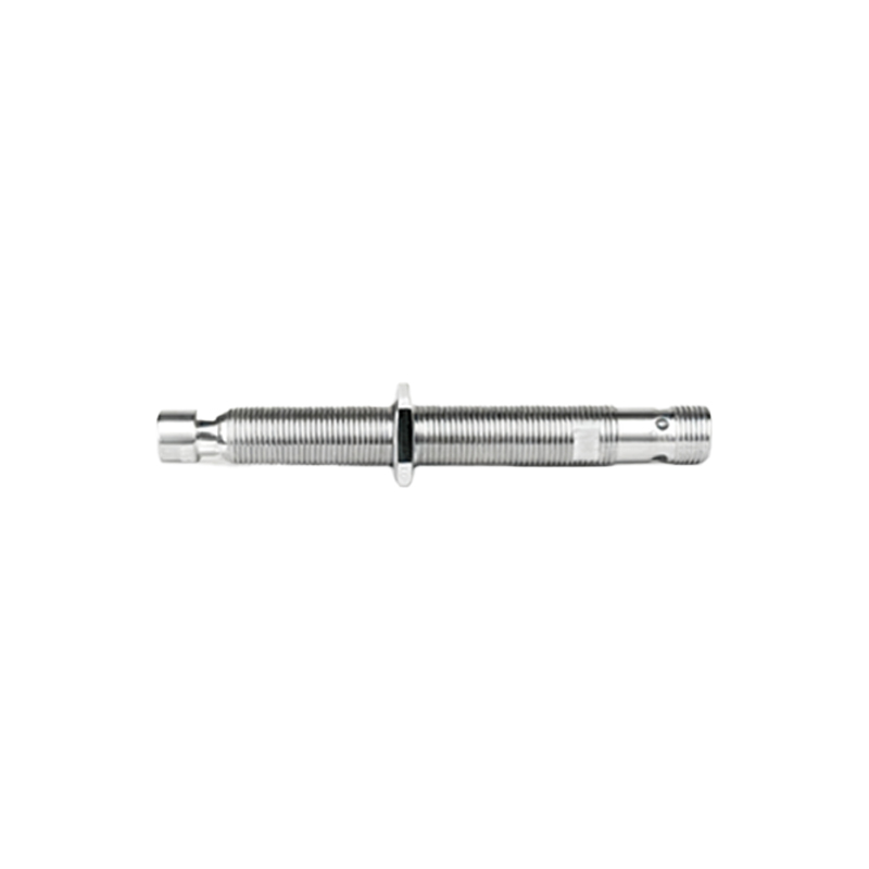
Installation factors also impact connectivity. Maintain the recommended sensing distance, as objects too close or far can cause false triggers. Avoid mounting sensors near metallic surfaces unless designed for such environments, as this can affect detection ranges. Regularly inspect connections for corrosion or loose wires, which are common causes of failure.
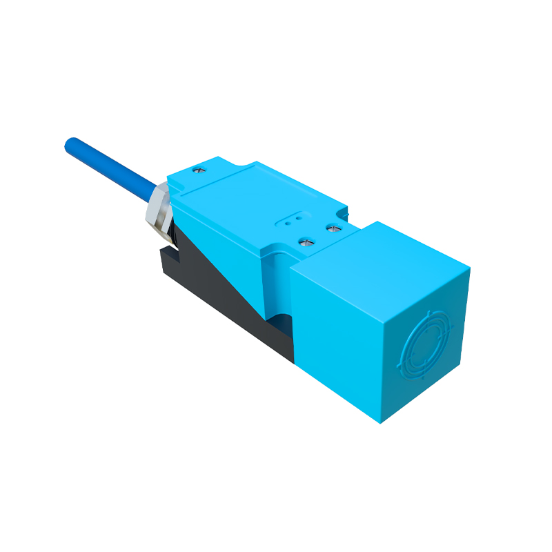
Troubleshooting connection issues involves systematic checks. First, confirm power supply voltage with a multimeter. If the sensor LED indicator is off, check wiring continuity. If the LED is on but no output signal, verify the load connection and controller input status. For intermittent operation, inspect for environmental factors like vibration or temperature extremes.
In summary, successful proximity sensor connection requires attention to electrical compatibility, wiring quality, and environmental conditions. By following manufacturer guidelines and industry best practices, users can achieve stable and accurate detection, enhancing system efficiency and reducing downtime.