In industrial automation and control systems, proximity sensors are indispensable components for non-contact detection of objects. Their reliability is paramount for ensuring smooth production flow, machine safety, and process consistency. However, instances of proximity sensor read failures are a common challenge faced by maintenance engineers and system integrators. A read failure, where the sensor does not correctly detect a target or provides an erratic signal, can lead to costly downtime, product defects, or even safety hazards. Understanding the root causes and implementing systematic diagnostic procedures is critical for rapid resolution.
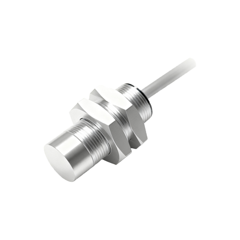
The primary categories of proximity sensor failures can be broadly classified into sensor-related issues, installation/environmental factors, and electrical/interference problems. Sensor-related failures often stem from internal component degradation. Over time, the oscillator coil in inductive sensors or the infrared LED in photoelectric sensors can weaken, reducing the effective sensing range. Physical damage to the sensing face, such as cracks or accumulation of metallic dust on inductive units, directly impedes function. Furthermore, a mismatch between the sensor's specifications and the application is a frequent oversight. Using a standard inductive sensor to detect aluminum, for instance, requires a factor correction as the sensing distance is reduced compared to steel.
Installation and environmental factors account for a significant portion of read failures. Incorrect mounting is a typical culprit. Insufficient clearance around the sensor body, known as the flush-mounting requirement for shielded inductive sensors, can cause false triggers or reduced range. Vibration can loosen mounting hardware, altering the critical gap between the sensor and the target. Environmental contaminants like oil, coolant, or conductive metal chips can coat the sensor face, creating a barrier. Extreme temperatures can also push the sensor beyond its rated operating specifications, causing internal circuitry to behave unpredictably or leading to thermal expansion that changes sensing distances.
Electrical and noise interference presents a more complex diagnostic scenario. Power supply issues are fundamental. A voltage supply that is too low, unstable, or has excessive ripple can prevent the sensor from operating correctly. Even if the sensor seems to activate, its output signal may be weak or inconsistent. Wiring errors, such as incorrect polarity for DC sensors, loose connections, or damaged cables causing short or open circuits, are common. Electrical noise from variable frequency drives (VFDs), welding equipment, or large motors can be inductively or capacitively coupled into sensor cables, causing erratic switching. Ensuring proper grounding, using shielded cables with the shield grounded at the controller end only, and separating signal lines from high-power cables are essential mitigation strategies.
A structured diagnostic approach is key to efficient troubleshooting. Begin with a visual and mechanical inspection: check for physical damage, contamination, and secure mounting. Verify the target's properties (material, size) against the sensor's specifications. Next, employ electrical measurement tools. Use a multimeter to check the supply voltage at the sensor terminals under load. Monitor the output signal with a multimeter or, preferably, an oscilloscope to see if it cleanly switches between the expected voltage levels. An oscilloscope can reveal noise superimposed on the signal. A simple operational test involves using a known good target at the rated sensing distance in a controlled setting to isolate the problem.
For persistent noise issues, consider installing ferrite cores on cables near the sensor or controller, or using signal conditioners or isolators. For harsh environments, select sensors with appropriate IP (Ingress Protection) ratings, higher temperature tolerances, and housings made of stainless steel or chemically resistant materials. Regular preventive maintenance, including scheduled cleaning of sensor faces and checking of electrical connections, can prevent many failure modes before they cause a line stoppage.
Ultimately, resolving proximity sensor read failures hinges on a methodical process that combines technical knowledge of sensor principles with practical diagnostic skills. By systematically eliminating potential causes—starting from the most common and simple to the more complex—engineers can minimize downtime and enhance system robustness. Investing in sensors with diagnostics capabilities, such as IO-Link technology, which provides detailed operational status and parameterization, is becoming a valuable strategy for modern smart factories to transition from reactive maintenance to predictive insights.