In the high-stakes environment of industrial automation, the assembly screen serves as the critical interface between machine logic and physical action. A key component ensuring this interaction is seamless and safe is the proximity sensor. When a proximity sensor on an assembly screen fails, it can trigger a cascade of operational disruptions, from minor production hiccups to complete line stoppages and potential safety hazards. Understanding the root causes, diagnostic procedures, and effective solutions is paramount for maintenance engineers and plant technicians.
Proximity sensors, typically inductive or capacitive types in these applications, function by detecting the presence or absence of a metallic or non-metallic target without physical contact. In an assembly screen context, they are often tasked with verifying part placement, confirming robotic arm positions, or ensuring safety guards are closed. A failure manifests in several telltale signs: erratic screen responses, false "part present" or "part absent" signals, failure to initiate the next assembly sequence, or persistent fault alarms on the Human-Machine Interface (HMI). The machine may enter a failsafe mode, halting operation entirely.
Diagnosing a faulty proximity sensor requires a systematic approach. First, consult the machine's diagnostic history and error codes on the HMI; modern PLCs often log specific sensor-related faults. Visual inspection is the next critical step. Look for obvious physical damage to the sensor housing or cable. Check for contamination buildup—metal shavings, oil, coolant, or dust—on the sensor's active face, which can attenuate or block its sensing field. Ensure the target object is within the sensor's specified sensing range and is of the correct material and size.
Electrical verification follows. Using a multimeter, check the supply voltage at the sensor's connector to confirm it matches specifications (commonly 10-30V DC). A voltage drop could indicate a failing power supply or high resistance in the wiring. Next, monitor the sensor's output signal. For a DC PNP (sourcing) sensor, the output should swing to near supply voltage when a target is present and drop to near 0V when absent (for normally open configuration). An inconsistent or absent signal change points to sensor failure. Oscilloscopes can reveal noisy or unstable output signals not visible on a multimeter. Importantly, also check the load (often a PLC input module) and the integrity of all connections, including grounding. Loose terminals or corroded contacts are frequent culprits.
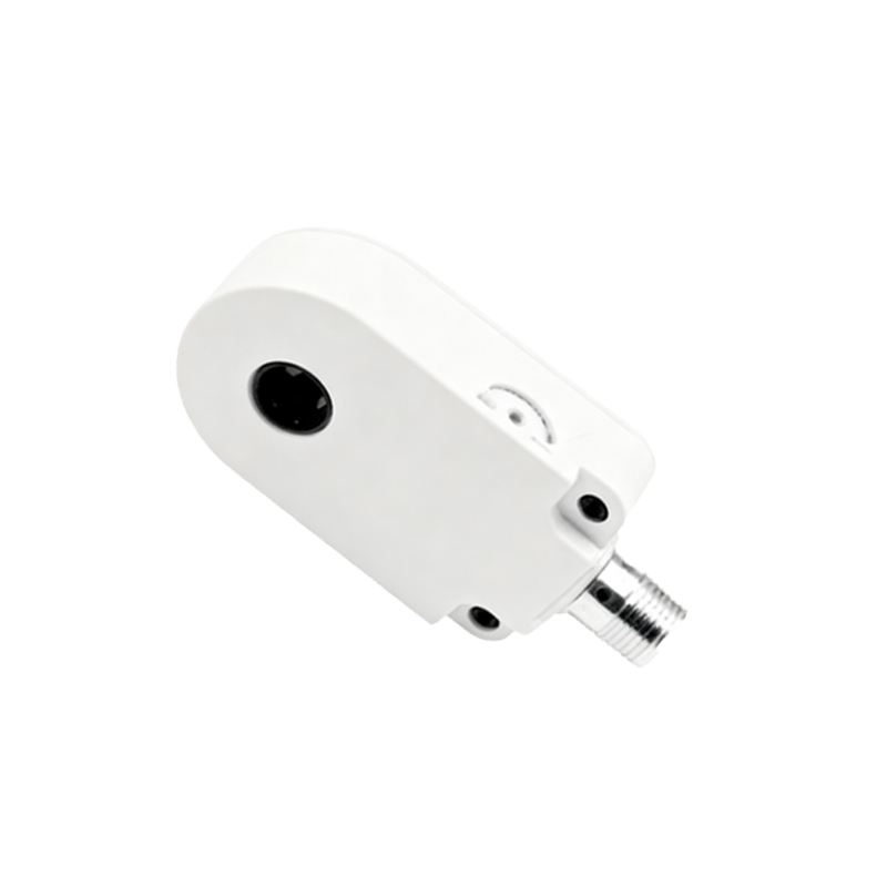
Environmental factors are a major contributor to premature sensor failure. Excessive vibration can loosen internal components or connections. Temperature extremes beyond the sensor's rating can cause internal circuitry to drift or fail. Exposure to harsh chemicals can degrade housing materials and seals. Electrical noise from nearby variable frequency drives (VFDs), welding equipment, or large motors can induce false signals. Ensuring proper sensor selection for the environment, along with adequate shielding and filtering, is a preventive necessity.
Once a faulty sensor is confirmed, replacement is often the most efficient course. However, this is not merely a swap. Key steps must be followed: 1) Power down and lock out the equipment according to safety protocols (LOTO). 2) Note the exact sensor model, sensing type, sensing range, output type (PNP/NPN, NO/NC), and connection style. 3) During installation, ensure the new sensor is correctly mounted with proper alignment to the target. Maintain the recommended clearance from metal surfaces to prevent side-effects. 4) Securely connect the wiring, paying close attention to polarity for DC sensors. 5) After power-up, recalibrate or teach-in the sensor if required, and perform a full functional test through several machine cycles.
Preventive maintenance is the best defense against unscheduled downtime. Establish a regular schedule to clean sensor faces, check mounting integrity, and verify electrical connections. Keep a stock of critical spares based on Mean Time Between Failure (MTBF) data. Consider upgrading to sensors with higher IP ratings (for dust/water resistance) or with enhanced noise immunity if failures are recurrent in a specific location.
In conclusion, a failed proximity sensor on an assembly screen is a common but serious issue in industrial settings. A methodical diagnostic process—encompassing visual, electrical, and environmental checks—enables rapid identification of the fault. Adherence to proper replacement procedures and a robust preventive maintenance strategy are essential to maximize sensor lifespan and ensure the relentless, reliable operation of automated assembly lines. The goal is not just to fix the immediate problem, but to implement solutions that enhance overall system resilience.