In industrial automation and machinery design, the reliable connection between proximity sensors and control systems is critical for operational efficiency and safety. Aviation plugs, also known as circular connectors, are widely favored in harsh environments due to their robust construction, secure locking mechanisms, and excellent sealing against dust, moisture, and vibration. This guide details the professional methodology for wiring inductive or capacitive proximity sensors to aviation plugs, ensuring a durable and fault-free installation.
The first step involves meticulous preparation. Gather all necessary components: the proximity sensor (confirming its type, e.g., NPN normally open or PNP normally closed, and its voltage rating, typically 10-30V DC), the aviation plug connector set (comprising the plug and socket, with the appropriate number of pins, commonly 3-pin or 4-pin for sensors), suitable gauge stranded copper wire (often 0.34 mm² or 0.5 mm²), wire strippers, a crimping tool with correct terminals, a soldering iron (if soldering is specified), and a multimeter for verification. Always consult the manufacturer's datasheets for both the sensor and the connector to confirm pinouts, voltage/current ratings, and IP (Ingress Protection) ratings suitable for the application environment.
A standard 3-wire DC proximity sensor has three leads: brown (or red) for positive supply (+V), blue (or black) for negative supply (0V or common), and black (or white) for the output signal. The corresponding aviation plug will have pins numbered or labeled. A typical wiring scheme for a 3-pin plug mated to an NPN sensor is: Pin 1 (or A) connects to the sensor's brown wire (+V). Pin 2 (or B) connects to the sensor's blue wire (0V). Pin 3 (or C) connects to the sensor's black output wire. For a PNP sensor, the output is sourcing positive voltage, but the supply connections remain consistent. If using a 4-pin plug, the fourth pin is often unused or reserved for a diagnostic or second output signal. It is paramount to maintain this consistency across all sensor-connector pairs in a system.
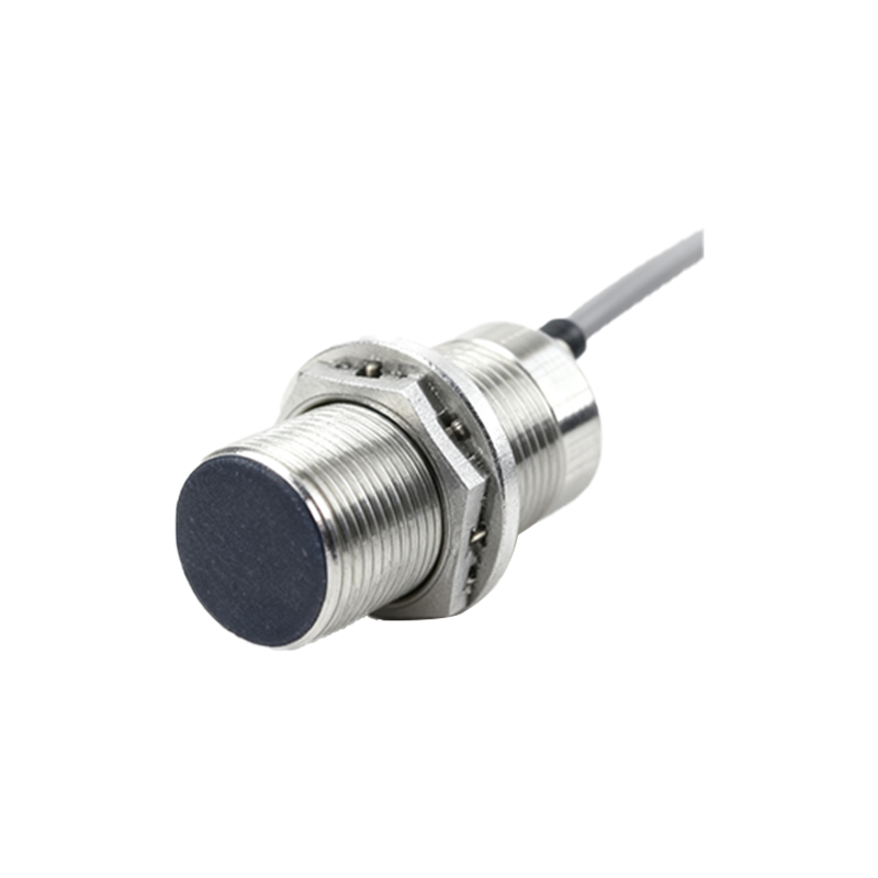
The termination process requires precision. Cut the sensor cable to the required length, leaving slack for strain relief. Strip a short length of insulation from each wire, exposing about 5-7 mm of conductor. Select the correct crimp terminals (e.g., female pin contacts for the plug side) and crimp them securely onto each wire using the calibrated tool. An improper crimp is a primary source of failure. Insert each crimped terminal into its designated cavity in the plug's insulator housing until a distinct click is heard or felt, indicating proper locking. For the socket (receptacle) side that will be panel-mounted and wired to the PLC or power supply, follow an identical procedure, ensuring the pin-to-pin correspondence matches the plug. For instance, Pin 1 on the plug must connect to Pin 1 on the socket. Always utilize the connector's built-in cable clamp or strain relief gland to secure the cable jacket, preventing tension from transferring to the electrical connections.
Before final assembly and deployment, rigorous testing is non-negotiable. With the connector halves unmated, use a multimeter in continuity mode to check for any short circuits between adjacent pins on each half. Next, perform a continuity test from each sensor wire to its corresponding pin terminal to verify correct wiring. After mating the plug and socket, power the system cautiously. Measure the voltage between the supply pins at the sensor side to confirm correct polarity and level. Finally, actuate the sensor by bringing the target metal object within its sensing range. Use the multimeter to verify that the output pin switches as expected (e.g., for an NPN, the output voltage should pull down to near 0V when activated). Additionally, a functional test with the connected PLC or controller to confirm input registration is highly recommended.
Common pitfalls to avoid include incorrect pin assignment, which can damage the sensor or controller; failing to implement proper strain relief, leading to wire breakage; overlooking the IP rating, resulting in connector failure in wet/dirty conditions; and mixing up NPN and PNP sensor types with incompatible PLC input cards. For high-noise environments, consider using shielded cables and connecting the shield to ground only at the control panel end, avoiding ground loops.
In summary, wiring proximity sensors to aviation plugs is a fundamental yet vital skill in industrial electrical practice. Adherence to manufacturer specifications, disciplined crimping and assembly techniques, and thorough pre-commissioning testing are the pillars of a reliable connection. This approach minimizes downtime, enhances system safety, and ensures the longevity of both the sensor and the connectivity solution in demanding automation settings.