Proximity sensors are indispensable components in modern steering gear systems, providing critical feedback for position control, safety interlocks, and automated operations. Their primary function is to detect the presence or absence of a target object without physical contact, typically the rudder stock, tiller arm, or specific mechanical stops within the steering gear assembly. This non-contact detection ensures high reliability, long service life, and minimal maintenance, which are paramount in demanding marine and industrial applications.
The core working principle revolves around electromagnetic or electromagnetic field disturbance. The most common types used in heavy-duty steering gears are inductive and capacitive proximity sensors.
Inductive Proximity Sensors:
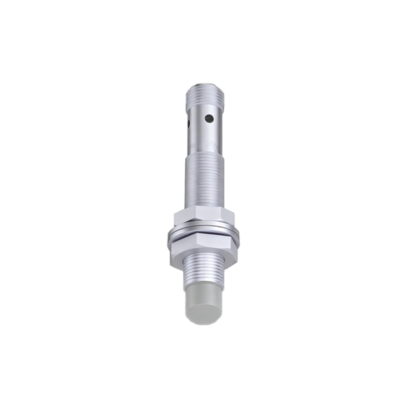
These sensors are predominantly used for detecting metallic targets, such as the steel components of a rudder stock or actuator. The heart of an inductive sensor is a coil wound around a ferrite core, connected to an oscillator circuit. When energized, the oscillator generates a high-frequency electromagnetic field that radiates from the active face of the sensor. In the absence of a conductive target, the oscillator operates at a baseline amplitude. When a metallic target enters this field, eddy currents are induced on the target's surface. These eddy currents draw energy from the oscillator circuit, causing a measurable drop in its oscillation amplitude. This amplitude change is detected by a threshold circuit, which subsequently triggers a solid-state switch (like a transistor) to change the output state (e.g., from OFF to ON). This signal is then sent to the steering gear control unit (SGCU) or programmable logic controller (PLC), indicating the rudder's position—for instance, at "mid-ships," "hard port," or "hard starboard."
Capacitive Proximity Sensors:
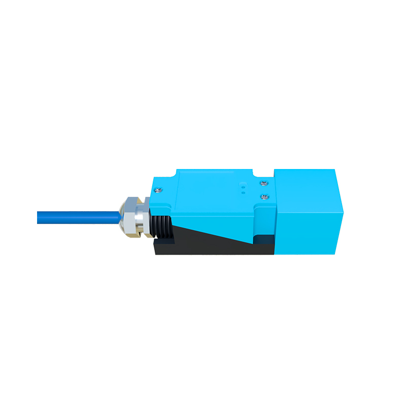
While less common for pure metal detection in steering gears, capacitive sensors are valuable for detecting non-metallic materials or when the target might have varying dielectric properties. They operate by generating an electrostatic field. The sensor's active face and the target act as two plates of a capacitor. As the target approaches, the capacitance between the "plates" increases. An internal circuit monitors this capacitance change. When it exceeds a preset threshold, the output state switches. In steering systems, this could be used to detect the presence of a composite material or to sense fluid levels in hydraulic reservoirs associated with the gear.
Key Components in a Diagram:
A standard explanatory diagram would illustrate:
1. Sensor Housing: Robust, often stainless steel or nickel-plated brass, providing IP67/IP69K protection against water, oil, and vibration.
2. Ferrite Core & Coil: The central inductive element.
3. Oscillator Circuit: Generates the high-frequency field.
4. Demodulator/Amplifier: Converts the minute amplitude change into a usable signal.
5. Trigger/Schmitt Trigger Circuit: Provides a clean, hysteresis-based switching action to prevent signal chatter.
6. Output Stage: Typically a PNP/NPN transistor or a solid-state relay providing a discrete signal.
7. LED Indicator: For visual status (power and output activation).
8. Target: The metallic part of the steering gear (e.g., a flange on the rudder stock) moving into the sensing range.
Integration in Steering Gear Control:
In a typical electro-hydraulic steering gear, two or more proximity sensors are strategically mounted on the hydraulic cylinder or rotary vane assembly. Their signals form a critical part of the closed-loop feedback system. The SGCU continuously monitors these sensors to determine the actual rudder angle. This is compared with the ordered rudder angle from the bridge's steering wheel or autopilot. Any discrepancy triggers the hydraulic power unit to move the actuators until the sensor feedback matches the command, ensuring precise angular control. They also serve as limit switches to prevent mechanical overtravel, which could damage the gear or the ship's hull.
Advantages for Marine Applications:
Non-contact Sensing: Eliminates wear and tear from mechanical limit switches.
High Switching Frequency: Can detect very fast movements, suitable for dynamic steering responses.
Environmental Resilience: Unaffected by dirt, grease, or moisture (when properly sealed), unlike optical sensors.
Fail-safe Design: Modern sensors offer short-circuit and overload protection, with diagnostics fed back to the control system.
Understanding the principle behind these sensors is crucial for engineers during system design, troubleshooting, and maintenance. For instance, incorrect mounting (insufficient clearance from metal surrounds), a wrong sensor type (e.g., using a standard sensor where a weld-field immune type is needed), or a damaged target can lead to erratic rudder response or system alarms. Regular