In the realm of industrial automation and control systems, inductive proximity sensors are indispensable components for non-contact detection of metallic objects. These sensors operate based on the principle of electromagnetic induction, offering reliable performance in harsh environments. This article delves into the working principle diagram of an inductive proximity sensor, breaking down its key components and operational stages to provide a clear understanding for engineers and technicians.
At the core of an inductive proximity sensor lies an oscillator circuit, a demodulator, a trigger circuit, and an output stage, all encapsulated within a robust housing. The oscillator generates a high-frequency electromagnetic field that radiates from the sensor's active face, typically made of ferrite material. When a metallic object enters this field, eddy currents are induced on the surface of the metal due to Faraday's law of electromagnetic induction. These eddy currents draw energy from the oscillator, causing a reduction in the amplitude of the oscillations. This change is detected by the demodulator, which converts the amplitude variation into a DC signal.
The DC signal is then fed into the trigger circuit, where it is compared to a predefined threshold. If the signal exceeds this threshold, indicating the presence of a metal object within the sensing range, the trigger activates the output stage. Depending on the sensor type, the output can be a switching signal—either normally open (NO) or normally closed (NC)—in forms such as NPN, PNP, or analog outputs. The output stage interfaces with control systems like PLCs (Programmable Logic Controllers) to initiate actions such as stopping a conveyor belt, counting parts, or positioning machinery.
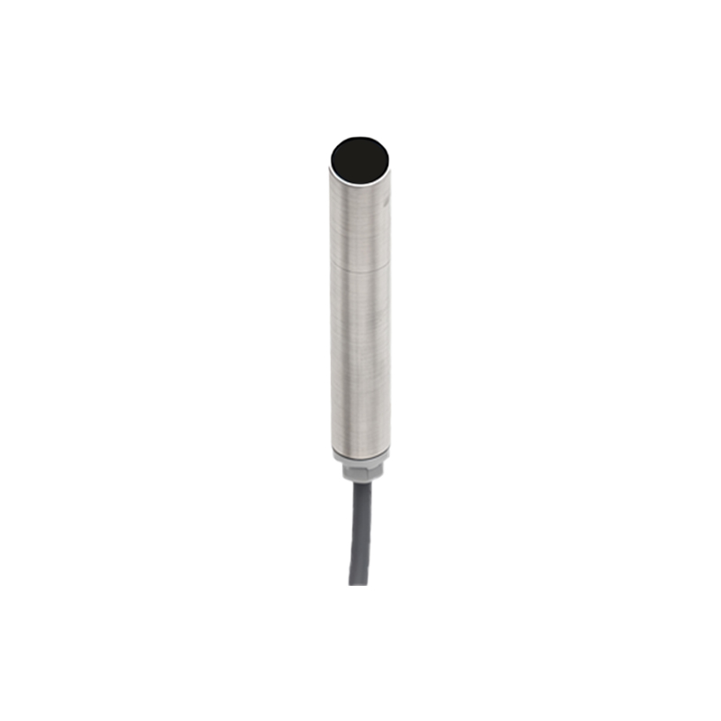
A typical working principle diagram illustrates these components in a block format, showing the flow from the oscillator to the output. The diagram often includes labels for the sensing coil, oscillator coil, and the metallic target, along with arrows indicating the direction of energy flow. Key parameters depicted may include the sensing distance, which varies based on the metal type (e.g., steel, aluminum, or copper) due to differences in conductivity and permeability. For instance, steel, with higher permeability, typically allows for longer sensing ranges compared to non-ferrous metals like aluminum.
In practice, inductive proximity sensors are valued for their durability, as they have no moving parts and are resistant to dust, moisture, and vibration. They are commonly used in applications such as machine tooling, automotive assembly lines, and material handling systems. Engineers must consider factors like the sensor's frequency response, which affects its ability to detect fast-moving objects, and the hysteresis effect, which prevents output chatter when the target is near the sensing limit.
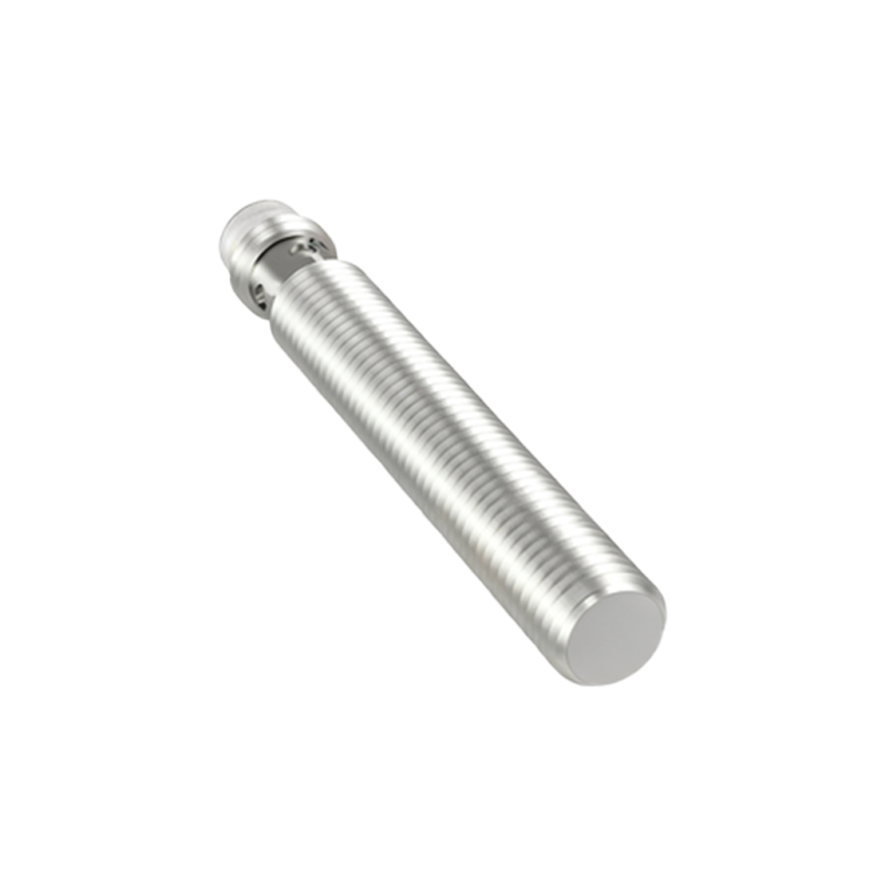
To optimize performance, the working principle diagram may also highlight installation guidelines, such as maintaining proper clearance from other metal surfaces to avoid false triggers. Additionally, modern sensors incorporate features like short-circuit protection and temperature compensation, enhancing their reliability in diverse industrial settings. By understanding the diagram and underlying principles, professionals can select and deploy these sensors effectively, ensuring efficient and safe automation processes.
In summary, the working principle diagram of an inductive proximity sensor serves as a visual aid to comprehend its electromagnetic operation, from field generation to signal output. Mastery of this diagram empowers engineers to troubleshoot issues, customize setups, and innovate in automation projects, driving productivity in the electrical and manufacturing industries.